How to Use JSY-MK-194G 2 split cores: Examples, Pinouts, and Specs
Introduction
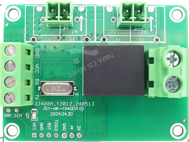
The JSY-MK-194G is a current transformer manufactured by JianSiYan Metering. It is designed for measuring alternating current (AC) in electrical systems. This component features two split cores, enabling easy installation around existing conductors without requiring disconnection of the circuit. The JSY-MK-194G is ideal for applications where non-invasive current measurement is required.
Explore Projects Built with JSY-MK-194G 2 split cores

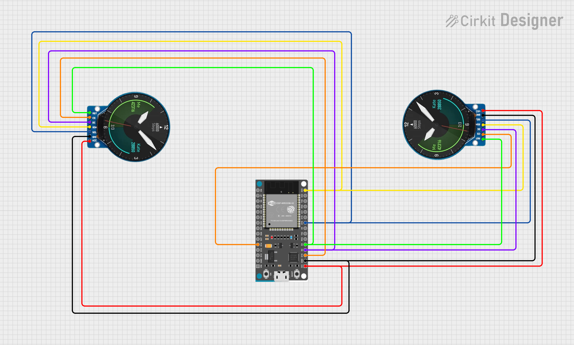
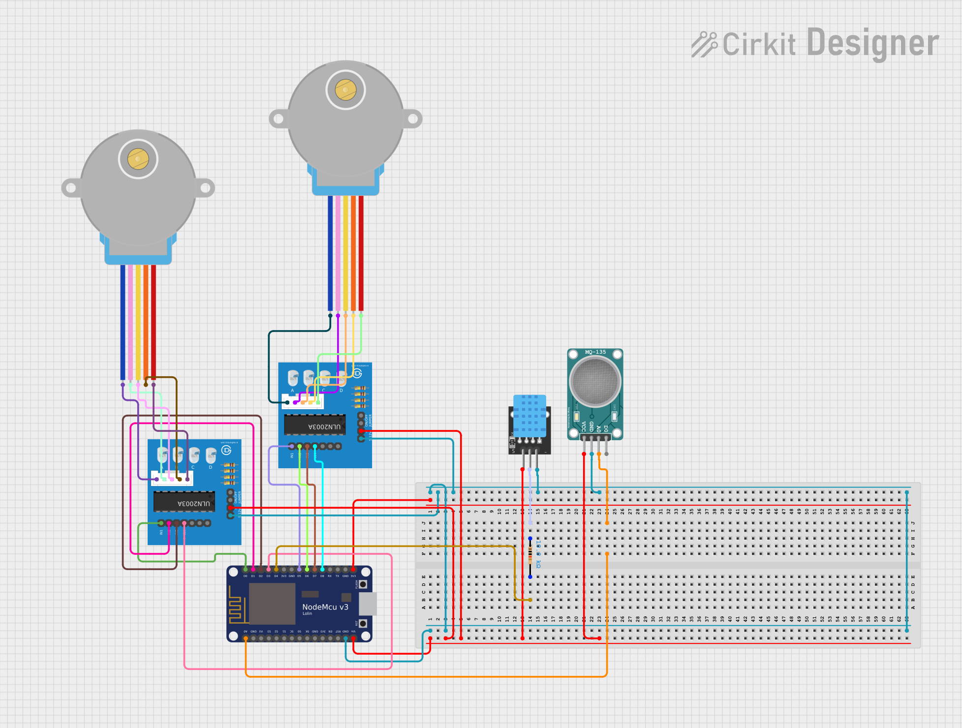
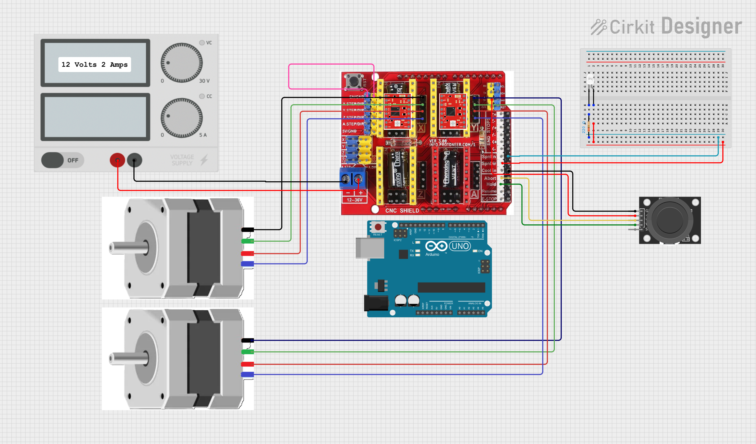
Explore Projects Built with JSY-MK-194G 2 split cores
Common Applications and Use Cases
- Energy monitoring systems
- Industrial equipment diagnostics
- Power quality analysis
- Smart grid and IoT energy solutions
- Retrofitting existing electrical installations for current measurement
Technical Specifications
The following table outlines the key technical details of the JSY-MK-194G:
| Parameter | Value |
|---|---|
| Manufacturer Part ID | JSY-MK-194G |
| Core Type | Split-core (2 cores) |
| Rated Input Current | 0–200 A AC |
| Output Signal | 0–5 V AC (proportional to input) |
| Accuracy Class | ±1% |
| Frequency Range | 50 Hz – 60 Hz |
| Insulation Voltage | 3 kV |
| Operating Temperature | -25°C to +70°C |
| Core Material | Ferrite |
| Dimensions | 94 mm x 50 mm x 26 mm |
| Weight | 250 g |
Pin Configuration and Descriptions
The JSY-MK-194G has a simple interface with three output wires. The pinout is described in the table below:
| Wire Color | Function | Description |
|---|---|---|
| Red | Signal Output (Positive) | Provides the AC voltage signal proportional to the measured current. |
| Black | Signal Output (Negative) | Acts as the ground reference for the output signal. |
| Green | Shield/Ground | Optional connection for shielding to reduce noise. |
Usage Instructions
How to Use the JSY-MK-194G in a Circuit
Installation:
- Open the split cores of the transformer.
- Place the cores around the conductor carrying the AC current to be measured.
- Ensure the cores are securely closed to maintain measurement accuracy.
Connection:
- Connect the red wire to the positive input of your measurement device (e.g., ADC or multimeter).
- Connect the black wire to the ground of your measurement device.
- Optionally, connect the green wire to the system ground to reduce noise.
Calibration:
- Verify the output signal using a known current source.
- Adjust the scaling factor in your measurement system to match the rated input/output ratio.
Important Considerations and Best Practices
- Ensure the conductor being measured is carrying AC current within the rated range (0–200 A).
- Avoid placing the transformer near strong magnetic fields or high-frequency noise sources.
- Always close the split cores completely to prevent measurement errors.
- Use proper insulation and grounding to ensure safety and signal integrity.
Example: Using JSY-MK-194G with an Arduino UNO
The JSY-MK-194G can be connected to an Arduino UNO for current measurement. Below is an example code snippet:
// Example: Reading AC current using JSY-MK-194G and Arduino UNO
// Connect the red wire to A0, black wire to GND, and green wire to GND (optional).

const int sensorPin = A0;  // Analog pin connected to JSY-MK-194G output
const float calibrationFactor = 40.0; // Adjust based on your setup (e.g., 200A = 5V)

void setup() {
  Serial.begin(9600);  // Initialize serial communication
}

void loop() {
  int sensorValue = analogRead(sensorPin);  // Read the analog value
  float voltage = (sensorValue / 1023.0) * 5.0;  // Convert to voltage (0-5V)
  float current = voltage * calibrationFactor;  // Calculate current in Amperes

  // Print the measured current to the Serial Monitor
  Serial.print("Measured Current: ");
  Serial.print(current);
  Serial.println(" A");

  delay(1000);  // Wait for 1 second before the next reading
}
Note: The calibrationFactor should be adjusted based on the specific characteristics of your setup and the rated input/output ratio of the transformer.
Troubleshooting and FAQs
Common Issues and Solutions
No Output Signal:
- Ensure the split cores are fully closed and properly aligned.
- Verify that the conductor being measured is carrying AC current within the rated range.
Inaccurate Measurements:
- Check for loose or improper connections.
- Ensure the transformer is not exposed to external magnetic interference.
- Calibrate the system using a known current source.
Noise in the Output Signal:
- Connect the green wire to the system ground to reduce noise.
- Use shielded cables for the output connections.
FAQs
Q: Can the JSY-MK-194G measure DC current?
A: No, the JSY-MK-194G is designed for AC current measurement only.
Q: What happens if the current exceeds 200 A?
A: Exceeding the rated current may result in inaccurate measurements or damage to the transformer.
Q: Can I use the JSY-MK-194G outdoors?
A: The transformer is not weatherproof. If outdoor use is required, ensure it is housed in a suitable enclosure.
Q: How do I clean the split cores?
A: Use a soft, dry cloth to clean the cores. Avoid using liquids or abrasive materials.
This documentation provides all the necessary details to effectively use the JSY-MK-194G 2 split cores current transformer in your projects. For further assistance, refer to the manufacturer's datasheet or contact JianSiYan Metering.