Cirkit Designer Logo
Cirkit Designer
Your all-in-one circuit design IDE
Home / 
Component Documentation

How to Use Hall Effect Magnetic Sensor Module: Examples, Pinouts, and Specs

Image of Hall Effect Magnetic Sensor Module
Cirkit Designer LogoDesign with Hall Effect Magnetic Sensor Module in Cirkit Designer

Introduction

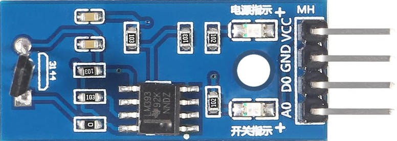
The Hall Effect Magnetic Sensor Module (Manufacturer: HiLetgo, Part ID: 3-01-1193) is a versatile electronic component designed to detect the presence and strength of a magnetic field. It operates based on the Hall effect, which generates a voltage difference across a conductor when it is exposed to a magnetic field. This module is widely used in applications such as position sensing, proximity detection, speed measurement, and current sensing.

Explore Projects Built with Hall Effect Magnetic Sensor Module

Use Cirkit Designer to design, explore, and prototype these projects online. Some projects support real-time simulation. Click "Open Project" to start designing instantly!
Magnetic Field-Activated Solenoid Array with Arduino Control
Image of Railgun: A project utilizing Hall Effect Magnetic Sensor Module in a practical application
This circuit is designed to use Hall effect sensors for magnetic field detection, interfaced with an Arduino UNO microcontroller to control an array of solenoids through MOSFETs. It includes user interface elements such as a tactile switch and LED, and features flyback diodes for solenoid protection.
Cirkit Designer LogoOpen Project in Cirkit Designer
Arduino Nano 33 BLE Magnetic Levitation System with Hall Sensor Feedback and Status LED Indicator
Image of LEVITRON: A project utilizing Hall Effect Magnetic Sensor Module in a practical application
This circuit is designed for a magnetic levitation system that uses a Hall sensor to detect magnetic field strength and a TIP120 transistor to control the current through a levitating coil. An Arduino Nano 33 BLE microcontroller reads the sensor and adjusts the coil current via PWM to maintain levitation, while an LED indicates the system's status. The circuit includes power management with 5V DC sources and protective components like diodes and resistors for current control and indication.
Cirkit Designer LogoOpen Project in Cirkit Designer
Arduino Nano ESP32 Hall Sensor Interface with LCD Display
Image of hall effect + speedometer: A project utilizing Hall Effect Magnetic Sensor Module in a practical application
This circuit includes a Hall sensor connected to an Arduino Nano ESP32 microcontroller, which is likely used to detect magnetic fields and send the data to the microcontroller on pin D12. The Arduino is also interfaced with an LCD display, with connections for power, ground, control (RS, E), and data (DB4-DB7) to display information. The absence of code suggests that the microcontroller's behavior is not defined in this context, but it is set up to read the Hall sensor and output to the LCD.
Cirkit Designer LogoOpen Project in Cirkit Designer
Arduino UNO-Based Battery-Powered Robotic System with Ultrasonic Sensors and Magnetometer
Image of Autonomous Mobile robot v1: A project utilizing Hall Effect Magnetic Sensor Module in a practical application
This circuit is a sensor-based robotic system controlled by an Arduino UNO. It includes three HC-SR04 ultrasonic sensors for distance measurement, a QMC5883L magnetometer for orientation detection, and an L298N motor driver to control two DC motors, all powered by a Li-ion 18650 battery.
Cirkit Designer LogoOpen Project in Cirkit Designer

Explore Projects Built with Hall Effect Magnetic Sensor Module

Use Cirkit Designer to design, explore, and prototype these projects online. Some projects support real-time simulation. Click "Open Project" to start designing instantly!
Image of Railgun: A project utilizing Hall Effect Magnetic Sensor Module in a practical application
Magnetic Field-Activated Solenoid Array with Arduino Control
This circuit is designed to use Hall effect sensors for magnetic field detection, interfaced with an Arduino UNO microcontroller to control an array of solenoids through MOSFETs. It includes user interface elements such as a tactile switch and LED, and features flyback diodes for solenoid protection.
Cirkit Designer LogoOpen Project in Cirkit Designer
Image of LEVITRON: A project utilizing Hall Effect Magnetic Sensor Module in a practical application
Arduino Nano 33 BLE Magnetic Levitation System with Hall Sensor Feedback and Status LED Indicator
This circuit is designed for a magnetic levitation system that uses a Hall sensor to detect magnetic field strength and a TIP120 transistor to control the current through a levitating coil. An Arduino Nano 33 BLE microcontroller reads the sensor and adjusts the coil current via PWM to maintain levitation, while an LED indicates the system's status. The circuit includes power management with 5V DC sources and protective components like diodes and resistors for current control and indication.
Cirkit Designer LogoOpen Project in Cirkit Designer
Image of hall effect + speedometer: A project utilizing Hall Effect Magnetic Sensor Module in a practical application
Arduino Nano ESP32 Hall Sensor Interface with LCD Display
This circuit includes a Hall sensor connected to an Arduino Nano ESP32 microcontroller, which is likely used to detect magnetic fields and send the data to the microcontroller on pin D12. The Arduino is also interfaced with an LCD display, with connections for power, ground, control (RS, E), and data (DB4-DB7) to display information. The absence of code suggests that the microcontroller's behavior is not defined in this context, but it is set up to read the Hall sensor and output to the LCD.
Cirkit Designer LogoOpen Project in Cirkit Designer
Image of Autonomous Mobile robot v1: A project utilizing Hall Effect Magnetic Sensor Module in a practical application
Arduino UNO-Based Battery-Powered Robotic System with Ultrasonic Sensors and Magnetometer
This circuit is a sensor-based robotic system controlled by an Arduino UNO. It includes three HC-SR04 ultrasonic sensors for distance measurement, a QMC5883L magnetometer for orientation detection, and an L298N motor driver to control two DC motors, all powered by a Li-ion 18650 battery.
Cirkit Designer LogoOpen Project in Cirkit Designer

Common Applications

  • Position Sensing: Detecting the position of moving parts in machinery.
  • Proximity Detection: Identifying the presence of magnetic objects.
  • Speed Measurement: Measuring the rotational speed of motors or wheels.
  • Current Measurement: Monitoring current flow in circuits using magnetic fields.

Technical Specifications

The following table outlines the key technical details of the HiLetgo Hall Effect Magnetic Sensor Module:

Parameter Specification
Operating Voltage 3.3V to 5V DC
Output Type Digital (High/Low)
Sensitivity Detects magnetic fields > 3mT
Output Voltage (High) ~Vcc (3.3V or 5V, depending on input)
Output Voltage (Low) ~0V
Operating Temperature -40°C to +85°C
Dimensions 32mm x 14mm x 7mm

Pin Configuration and Descriptions

The module has three pins, as described in the table below:

Pin Name Description
1 VCC Power supply input (3.3V to 5V DC)
2 GND Ground connection
3 OUT Digital output pin (High when no magnetic field, Low when a magnetic field is detected)

Usage Instructions

How to Use the Component in a Circuit

  1. Power the Module: Connect the VCC pin to a 3.3V or 5V DC power source and the GND pin to the ground of your circuit.
  2. Connect the Output: Attach the OUT pin to a digital input pin of your microcontroller or other logic-level device.
  3. Place the Magnet: Position a magnet near the sensor. The module will output a LOW signal when a magnetic field is detected and a HIGH signal when no magnetic field is present.

Important Considerations and Best Practices

  • Magnet Placement: Ensure the magnet is aligned properly with the sensor for accurate detection.
  • Power Supply: Use a stable power source to avoid erratic behavior.
  • Interference: Avoid placing the module near strong electromagnetic interference sources, as this may affect its performance.
  • Pull-up Resistor: If the output is connected to a microcontroller, ensure the input pin is configured with a pull-up resistor if required.

Example: Connecting to an Arduino UNO

Below is an example of how to use the Hall Effect Magnetic Sensor Module with an Arduino UNO:

Circuit Connections

  • Connect the VCC pin of the module to the 5V pin on the Arduino.
  • Connect the GND pin of the module to the GND pin on the Arduino.
  • Connect the OUT pin of the module to digital pin 2 on the Arduino.

Arduino Code

// Hall Effect Magnetic Sensor Module Example
// Manufacturer: HiLetgo, Part ID: 3-01-1193

const int sensorPin = 2;  // Digital pin connected to the OUT pin of the sensor
const int ledPin = 13;    // Built-in LED pin on Arduino

void setup() {
  pinMode(sensorPin, INPUT);  // Set sensor pin as input
  pinMode(ledPin, OUTPUT);    // Set LED pin as output
  Serial.begin(9600);         // Initialize serial communication
}

void loop() {
  int sensorState = digitalRead(sensorPin);  // Read the sensor output

  if (sensorState == LOW) {
    // Magnetic field detected
    digitalWrite(ledPin, HIGH);  // Turn on the LED
    Serial.println("Magnetic field detected!");
  } else {
    // No magnetic field detected
    digitalWrite(ledPin, LOW);   // Turn off the LED
    Serial.println("No magnetic field detected.");
  }

  delay(500);  // Wait for 500ms before the next reading
}

Troubleshooting and FAQs

Common Issues and Solutions

  1. No Output Signal:

    • Cause: Incorrect wiring or loose connections.
    • Solution: Double-check all connections, ensuring the VCC and GND pins are properly connected.
  2. Erratic Behavior:

    • Cause: Unstable power supply or electromagnetic interference.
    • Solution: Use a regulated power supply and keep the module away from interference sources.
  3. Sensor Not Detecting Magnetic Field:

    • Cause: Magnet is too weak or improperly aligned.
    • Solution: Use a stronger magnet and ensure proper alignment with the sensor.

FAQs

Q: Can this module detect both north and south poles of a magnet?
A: Yes, the module can detect both poles, but it does not differentiate between them.

Q: What is the maximum distance for magnetic field detection?
A: The detection range depends on the strength of the magnet. Typically, it can detect fields within a few centimeters.

Q: Can I use this module with a 3.3V microcontroller?
A: Yes, the module operates at both 3.3V and 5V, making it compatible with 3.3V microcontrollers like ESP32.

Q: Is the output signal analog or digital?
A: The output signal is digital, providing a HIGH or LOW state based on the presence of a magnetic field.