How to Use SparkFun RPI-1031 Tilt-a-Whirl Breakout: Examples, Pinouts, and Specs
Introduction
The SparkFun RPI-1031 Tilt-a-Whirl Breakout is a versatile sensor module that combines an accelerometer and gyroscope to measure tilt, rotation, and motion. It is specifically designed for compatibility with the Raspberry Pi and other microcontrollers, making it an ideal choice for robotics, gaming controllers, and motion detection projects.
Explore Projects Built with SparkFun RPI-1031 Tilt-a-Whirl Breakout
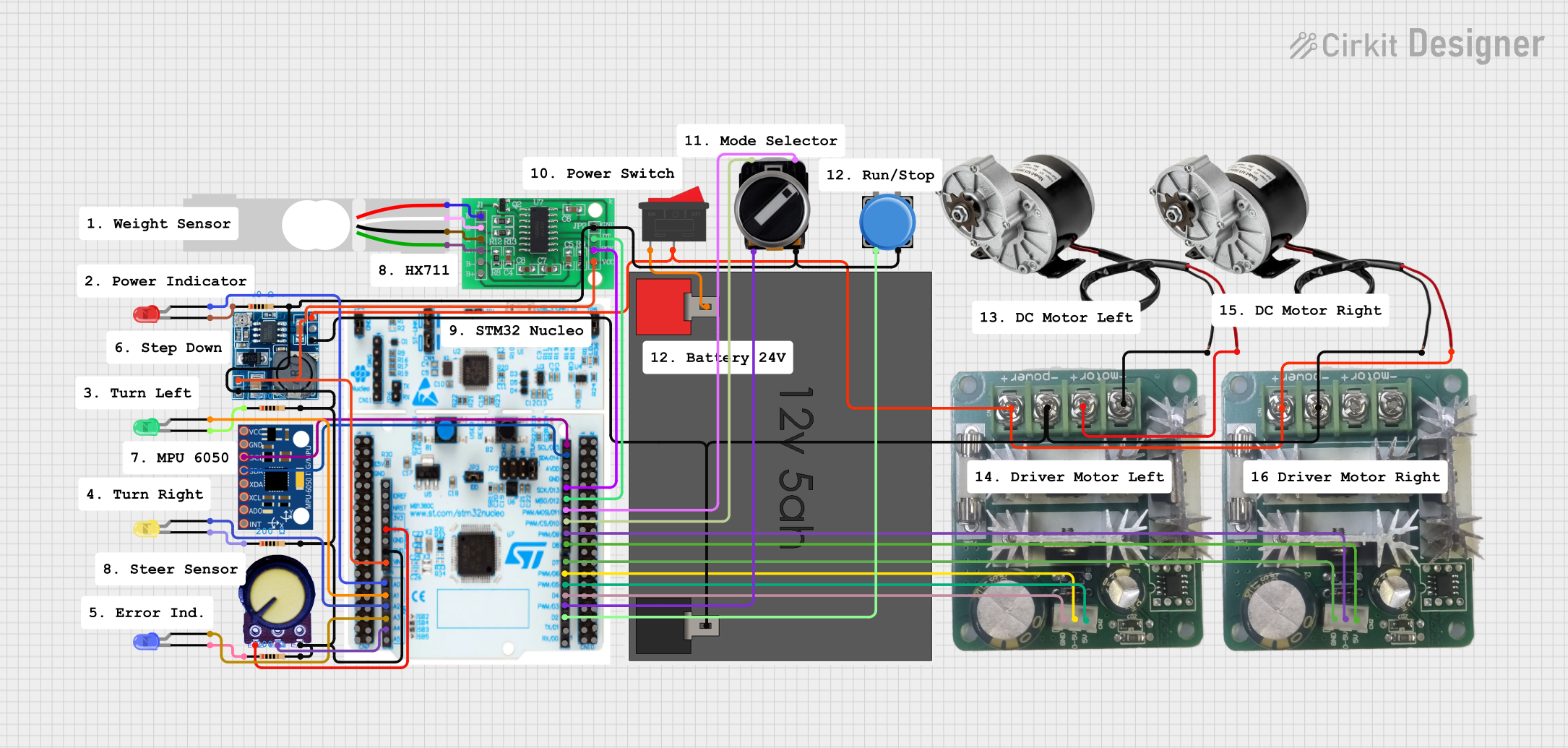
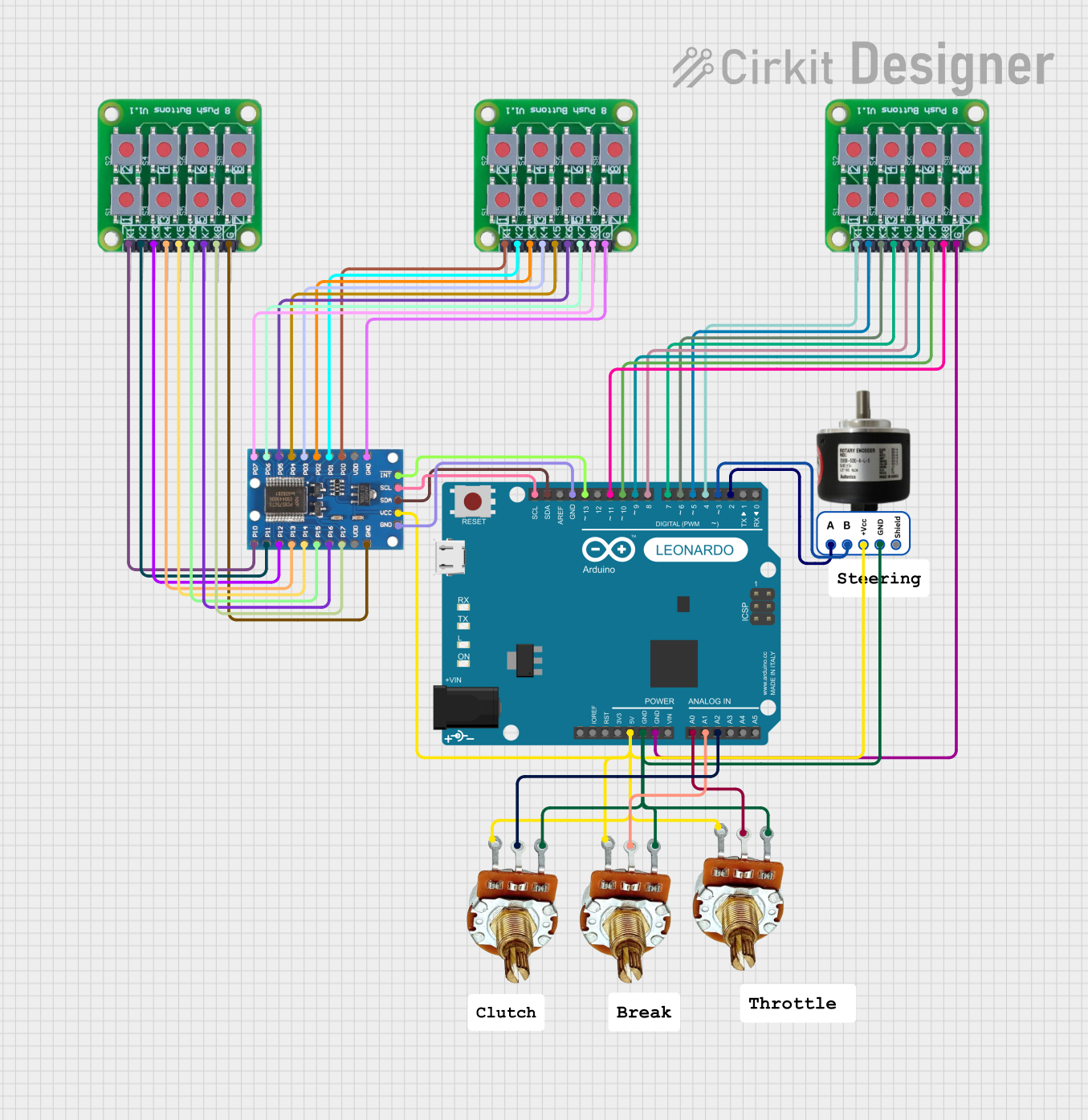
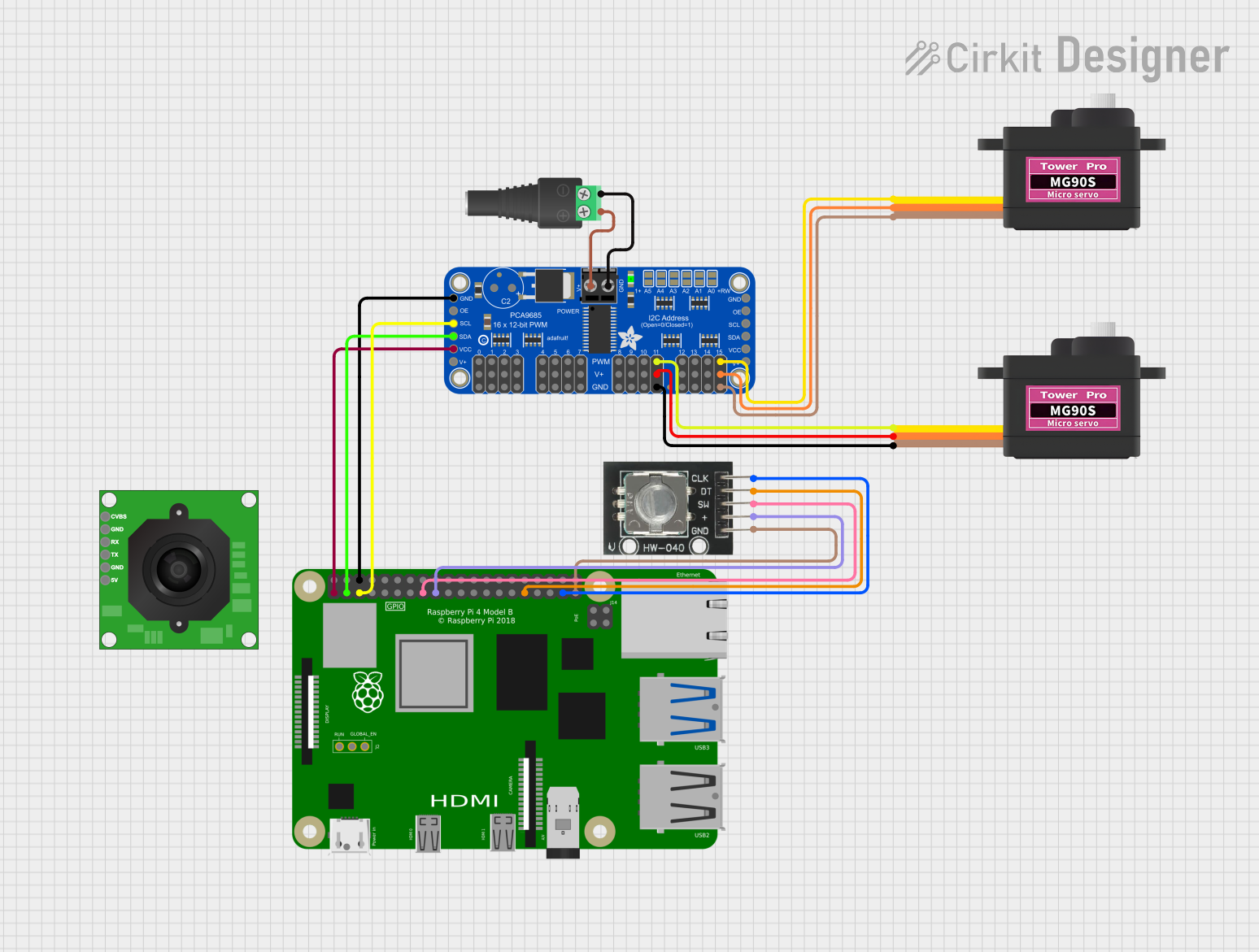
Explore Projects Built with SparkFun RPI-1031 Tilt-a-Whirl Breakout
Common Applications and Use Cases
- Robotics for balance and movement detection
- Gaming controllers for motion control
- Vehicle navigation systems for tilt and rotation measurement
- Fitness and health tracking devices
- Virtual reality (VR) and augmented reality (AR) systems
Technical Specifications
Key Technical Details
- Operating Voltage: 3.3V to 5V
- Output: Digital (I2C)
- Measurement Range:
- Accelerometer: ±3g
- Gyroscope: ±250, ±500, ±1000, ±2000°/sec
- Sensitivity:
- Accelerometer: Adjustable
- Gyroscope: Adjustable
- Dimensions: 25.4mm x 25.4mm
Pin Configuration and Descriptions
| Pin Number | Name | Description |
|---|---|---|
| 1 | VCC | Power supply (3.3V to 5V) |
| 2 | GND | Ground connection |
| 3 | SDA | I2C Data Line |
| 4 | SCL | I2C Clock Line |
| 5 | INT | Interrupt output (optional) |
Usage Instructions
How to Use the Component in a Circuit
Powering the Module:
- Connect the VCC pin to a 3.3V or 5V power supply.
- Connect the GND pin to the ground of your power supply.
Connecting to a Microcontroller:
- Connect the SDA and SCL pins to the I2C data and clock lines on your microcontroller.
Setting Up the Interrupt (Optional):
- If using the interrupt feature, connect the INT pin to an interrupt-capable GPIO pin on your microcontroller.
Important Considerations and Best Practices
- Ensure that the power supply voltage matches the module's requirements.
- Use pull-up resistors on the I2C lines if they are not already present on your microcontroller board.
- Avoid placing the module near magnetic fields or in environments with high vibration to prevent inaccurate readings.
- Calibrate the sensor for your specific application to achieve the best results.
Example Code for Arduino UNO
#include <Wire.h>

// RPI-1031 I2C address (check datasheet for your device's address)
#define RPI_1031_ADDRESS 0x68

void setup() {
  Wire.begin(); // Initialize I2C
  Serial.begin(9600); // Start serial communication at 9600 baud rate

  // Setup sensor configuration (if necessary)
  // Write to sensor registers using Wire library functions
}

void loop() {
  // Read sensor data
  // Process and output the data to the serial monitor
}

// Add functions to read and write to the sensor's registers
// as needed for your application.
Note: This example code is a template to initialize I2C communication and does not include specific register read/write functions. Refer to the RPI-1031 datasheet for detailed register information and modify the code accordingly.
Troubleshooting and FAQs
Common Issues Users Might Face
- Inaccurate Readings: Ensure the module is calibrated correctly and is not affected by external magnetic fields or vibrations.
- No Data on I2C: Check the connections and ensure pull-up resistors are in place. Also, verify that the correct I2C address is being used.
Solutions and Tips for Troubleshooting
- Calibration: Follow the calibration procedure outlined in the datasheet to adjust the sensor for your environment.
- I2C Scanning: Use an I2C scanner sketch to confirm the device's address and connectivity.
FAQs
Q: Can the RPI-1031 be used with an Arduino? A: Yes, the RPI-1031 can be interfaced with an Arduino using the I2C protocol.
Q: What is the purpose of the INT pin? A: The INT pin can be used to trigger an interrupt on the microcontroller when a certain event is detected by the sensor.
Q: How do I change the sensitivity of the accelerometer and gyroscope? A: Sensitivity settings can be adjusted by writing to the appropriate registers on the sensor. Refer to the datasheet for specific register settings.
Q: Is additional software or a library required to use the RPI-1031? A: While not strictly necessary, using a library specifically designed for the RPI-1031 can simplify programming and improve code readability.
Q: How do I ensure the module is properly powered? A: Use a multimeter to verify that the VCC and GND connections are supplying the correct voltage to the module.