How to Use Arduino 101: Examples, Pinouts, and Specs
Introduction
The Arduino 101 is a microcontroller board based on the Intel Curie module. It is designed for Internet of Things (IoT) applications and wearable devices, offering advanced features such as built-in Bluetooth Low Energy (BLE) capabilities and a 6-axis accelerometer/gyroscope. The board is ideal for projects requiring wireless communication, motion sensing, or real-time data processing.
Common applications of the Arduino 101 include:
- IoT devices and smart home systems
- Wearable technology
- Motion tracking and gesture recognition
- Educational projects and prototyping
- Wireless sensor networks
Explore Projects Built with Arduino 101

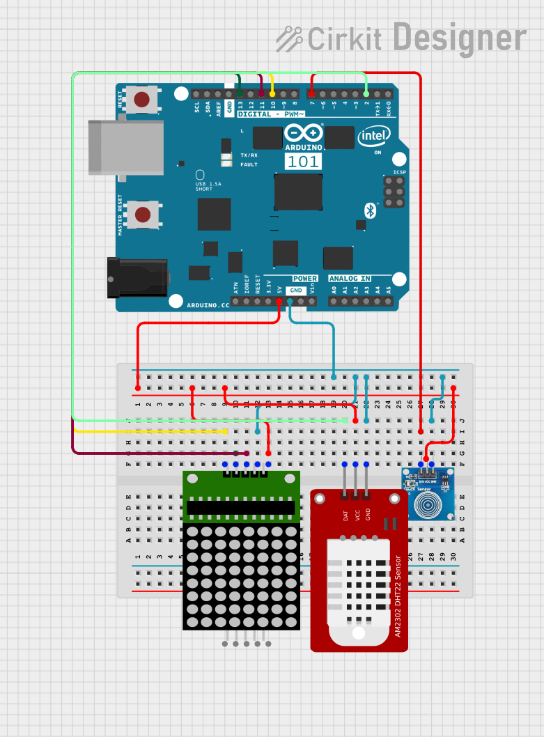
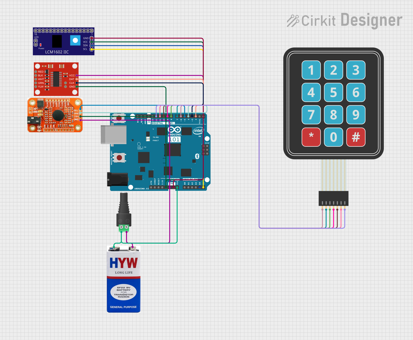
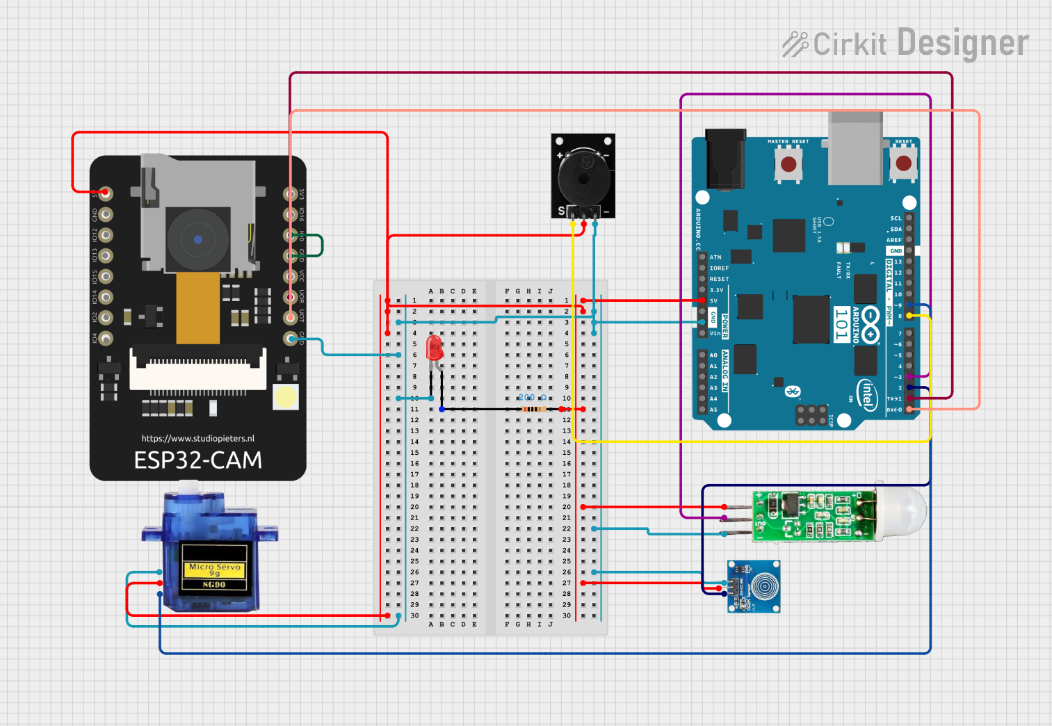
Explore Projects Built with Arduino 101
Technical Specifications
The Arduino 101 combines the ease of use of the Arduino platform with the power of the Intel Curie module. Below are the key technical details:
| Specification | Details |
|---|---|
| Microcontroller | Intel Curie module (32-bit Intel Quark SE SoC) |
| Operating Voltage | 3.3V |
| Input Voltage (recommended) | 7-12V |
| Input Voltage (limit) | 7-20V |
| Digital I/O Pins | 14 (of which 4 provide PWM output) |
| PWM Digital I/O Pins | 4 |
| Analog Input Pins | 6 |
| DC Current per I/O Pin | 20 mA |
| Flash Memory | 196 KB (for user applications) |
| SRAM | 24 KB |
| EEPROM | None |
| Clock Speed | 32 MHz |
| Bluetooth | Bluetooth Low Energy (BLE) |
| Sensors | 6-axis accelerometer/gyroscope |
| USB Connector | Micro USB |
| Dimensions | 68.6 mm x 53.4 mm |
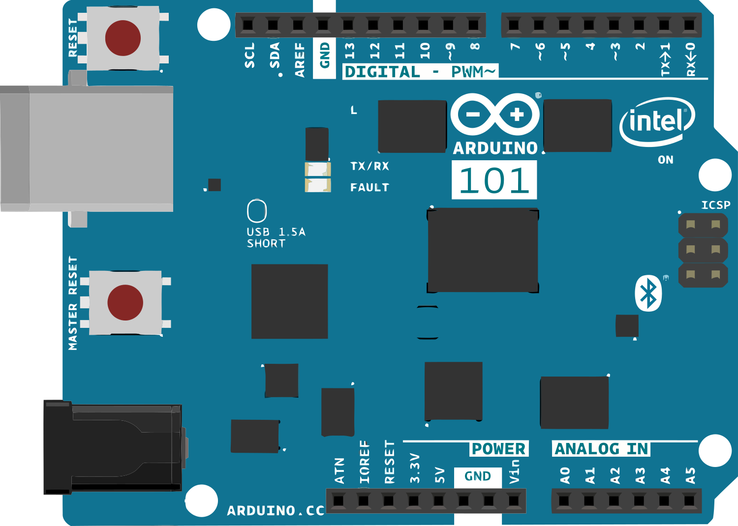
Pin Configuration and Descriptions
The Arduino 101 has a standard Arduino Uno form factor, making it compatible with most Arduino shields. Below is the pin configuration:
| Pin | Description |
|---|---|
| Digital Pins | Pins 0-13: General-purpose digital I/O pins. Pins 3, 5, 6, and 9 support PWM. |
| Analog Pins | Pins A0-A5: Analog input pins with a 10-bit resolution. |
| Power Pins | 3.3V, 5V, GND, and Vin: Power supply pins. |
| I2C Pins | A4 (SDA) and A5 (SCL): Used for I2C communication. |
| SPI Pins | 10 (SS), 11 (MOSI), 12 (MISO), 13 (SCK): Used for SPI communication. |
| UART Pins | 0 (RX) and 1 (TX): Used for serial communication. |
| Reset Pin | Resets the microcontroller. |
Usage Instructions
The Arduino 101 is programmed using the Arduino IDE, which supports the board natively. Follow these steps to use the Arduino 101 in a circuit:
Install the Arduino IDE:
- Download and install the latest version of the Arduino IDE from the official website.
- Open the IDE and go to
Tools > Board > Boards Manager. Search for "Intel Curie Boards" and install the package.
Connect the Arduino 101:
- Use a micro USB cable to connect the Arduino 101 to your computer.
- Select the correct board (
Arduino/Genuino 101) and port from theToolsmenu.
Write and Upload Code:
- Write your code in the Arduino IDE. Below is an example of using the built-in BLE to send data:
#include <CurieBLE.h> // Include the BLE library for Arduino 101

BLEPeripheral blePeripheral; // Create a BLE Peripheral object
BLEService customService("19B10000-E8F2-537E-4F6C-D104768A1214");
// Define a custom BLE service

BLECharacteristic customCharacteristic("19B10001-E8F2-537E-4F6C-D104768A1214",
                                       BLERead | BLEWrite, 20);
// Define a BLE characteristic with read and write permissions

void setup() {
  Serial.begin(9600); // Start serial communication
  blePeripheral.setLocalName("Arduino101"); // Set the BLE device name
  blePeripheral.setAdvertisedServiceUuid(customService.uuid());
  // Advertise the custom service
  blePeripheral.addAttribute(customService); // Add the service
  blePeripheral.addAttribute(customCharacteristic); // Add the characteristic
  blePeripheral.begin(); // Start BLE
  Serial.println("BLE device is now active!");
}

void loop() {
  BLEDevice central = blePeripheral.central();
  // Check if a central device is connected

  if (central) {
    Serial.print("Connected to central: ");
    Serial.println(central.address());
    while (central.connected()) {
      // Send data to the central device
      customCharacteristic.setValue("Hello from Arduino 101!");
      delay(1000); // Wait for 1 second
    }
    Serial.println("Disconnected from central.");
  }
}
- Power the Board:
- The Arduino 101 can be powered via the USB connection or an external power supply (7-12V recommended).
Important Considerations and Best Practices
- Voltage Levels: The Arduino 101 operates at 3.3V logic levels. Ensure that any external components connected to the board are compatible with 3.3V.
- BLE Range: The BLE range is limited to approximately 10 meters. Ensure that the central device is within range for reliable communication.
- Sensor Calibration: For accurate motion sensing, calibrate the 6-axis accelerometer/gyroscope before use.
Troubleshooting and FAQs
Common Issues
The board is not detected by the Arduino IDE:
- Ensure that the correct board (
Arduino/Genuino 101) and port are selected in theToolsmenu. - Check that the USB cable is functional and properly connected.
- Ensure that the correct board (
BLE is not working:
- Verify that the BLE library (
CurieBLE.h) is included in your code. - Ensure that the central device supports BLE and is within range.
- Verify that the BLE library (
Code upload fails:
- Press the reset button on the board and try uploading the code again.
- Check for any syntax errors in your code.
Tips for Troubleshooting
- Use the Serial Monitor in the Arduino IDE to debug your code and monitor BLE activity.
- Update the board's firmware if you encounter persistent issues. Instructions for updating the firmware can be found on the Arduino website.
FAQs
Q: Can I use Arduino shields with the Arduino 101?
A: Yes, the Arduino 101 has the same form factor as the Arduino Uno, making it compatible with most Arduino shields.
Q: Does the Arduino 101 support Wi-Fi?
A: No, the Arduino 101 does not have built-in Wi-Fi. However, you can use an external Wi-Fi module for wireless connectivity.
Q: How do I calibrate the accelerometer/gyroscope?
A: Use the appropriate libraries (e.g., CurieIMU.h) to calibrate the sensors. Refer to the library documentation for detailed instructions.
This concludes the documentation for the Arduino 101. For further assistance, visit the Arduino Forum.