
How to Use ICL7660 Charge-Pump Voltage Converter: Examples, Pinouts, and Specs
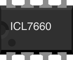
 Design with ICL7660 Charge-Pump Voltage Converter in Cirkit Designer
Introduction
The ICL7660 is a charge-pump voltage converter designed to generate a negative voltage from a positive voltage supply. It operates by transferring charge between capacitors, enabling efficient voltage inversion without the need for inductors. This makes the ICL7660 a compact and cost-effective solution for applications requiring a negative voltage rail.
Explore Projects Built with ICL7660 Charge-Pump Voltage Converter
 Open Project in Cirkit Designer
 Open Project in Cirkit Designer
 Open Project in Cirkit Designer
 Open Project in Cirkit Designer
Explore Projects Built with ICL7660 Charge-Pump Voltage Converter
Open Project in Cirkit DesignerOpen Project in Cirkit DesignerOpen Project in Cirkit DesignerOpen Project in Cirkit DesignerCommon Applications and Use Cases
- Generating negative voltage rails for operational amplifiers
- Biasing circuits in analog systems
- LCD contrast adjustment
- Low-power, portable devices requiring dual power supplies
- General-purpose voltage inversion in battery-powered systems
Technical Specifications
The ICL7660 is a versatile and efficient device with the following key specifications:
| Parameter | Value |
|---|---|
| Input Voltage Range (V+) | 1.5V to 10V |
| Output Voltage Range (V-) | -1.5V to -10V (approx. -V+) |
| Output Current (Iout) | Up to 20mA |
| Quiescent Current (Iq) | 200µA (typical) |
| Efficiency | ~98% (ideal conditions) |
| Operating Temperature Range | 0°C to +70°C |
| Package Types | DIP-8, SOIC-8 |
Pin Configuration and Descriptions
The ICL7660 is typically available in an 8-pin DIP or SOIC package. Below is the pinout and description:
| Pin Number | Pin Name | Description |
|---|---|---|
| 1 | V+ | Positive power supply input (1.5V to 10V). |
| 2 | CAP+ | Positive terminal of the external charge-pump capacitor. |
| 3 | GND | Ground (0V reference). |
| 4 | CAP- | Negative terminal of the external charge-pump capacitor. |
| 5 | VOUT | Negative voltage output (-V+). |
| 6 | LV | Low-voltage pin (connect to GND for input voltage < 3.5V). |
| 7 | OSC | Oscillator control pin (connect to GND for default frequency, or external clock). |
| 8 | V+ | Positive power supply input (same as Pin 1). |
Usage Instructions
How to Use the ICL7660 in a Circuit
- Power Supply: Connect the V+ pin to a positive voltage source (1.5V to 10V) and the GND pin to ground.
- Charge-Pump Capacitors:
- Connect a capacitor (typically 10µF) between CAP+ and CAP-.
- Connect another capacitor (10µF or higher) between VOUT and GND to stabilize the output voltage.
- Low Voltage Operation: If the input voltage is below 3.5V, connect the LV pin to GND to optimize performance.
- Oscillator Control: For standard operation, leave the OSC pin unconnected or connect it to GND. For custom oscillator frequencies, an external clock signal can be applied to this pin.
Example Circuit
Below is a basic circuit diagram for using the ICL7660 to generate a -5V output from a +5V input:
   +5V ----+------------------+------------------+
           |                  |                  |
          [C1]               [C2]               |
           |                  |                  |
          CAP+               VOUT               GND
           |                  |                  |
          CAP-               GND                |
           |                  |                  |
           +------------------+------------------+
- C1 and C2 are typically 10µF electrolytic capacitors.
Arduino UNO Example Code
The ICL7660 can be used in conjunction with an Arduino UNO to provide a negative voltage rail for analog circuits. Below is an example code snippet to demonstrate its use:
// Example: Using ICL7660 with Arduino UNO
// This code demonstrates how to read an analog signal that requires a negative
// voltage reference, powered by the ICL7660.

const int analogPin = A0; // Analog input pin connected to the signal

void setup() {
  Serial.begin(9600); // Initialize serial communication
  pinMode(analogPin, INPUT); // Set the analog pin as input
}

void loop() {
  int analogValue = analogRead(analogPin); // Read the analog signal
  float voltage = (analogValue / 1023.0) * 5.0; // Convert to voltage (0-5V range)

  // Print the voltage value to the Serial Monitor
  Serial.print("Analog Voltage: ");
  Serial.print(voltage);
  Serial.println(" V");

  delay(500); // Wait for 500ms before the next reading
}
Important Considerations and Best Practices
- Use low-ESR capacitors (e.g., tantalum or ceramic) for optimal performance.
- Ensure the input voltage does not exceed the maximum rating of 10V.
- For higher output currents, use larger capacitors to reduce ripple voltage.
- Avoid excessive load currents, as this can cause the output voltage to drop significantly.
- If using the OSC pin for an external clock, ensure the frequency is within the recommended range (10kHz to 100kHz).
Troubleshooting and FAQs
Common Issues and Solutions
Output Voltage is Incorrect or Unstable:
- Check the polarity and value of the capacitors.
- Ensure the capacitors are low-ESR and properly connected.
- Verify that the input voltage is within the specified range.
High Ripple on Output Voltage:
- Increase the capacitance of the output capacitor (VOUT to GND).
- Use capacitors with lower ESR for better filtering.
Device Overheating:
- Ensure the load current does not exceed the maximum rating (20mA).
- Verify that the input voltage is not too high.
No Output Voltage:
- Check all connections and ensure the device is powered correctly.
- Verify that the LV pin is connected to GND if the input voltage is below 3.5V.
FAQs
Q1: Can the ICL7660 provide a regulated output voltage?
A1: The ICL7660 does not provide precise voltage regulation. The output voltage is approximately equal to -V+, minus a small voltage drop due to internal resistance.
Q2: Can I use the ICL7660 with input voltages above 10V?
A2: No, the maximum input voltage is 10V. Exceeding this limit may damage the device.
Q3: What happens if I omit the LV pin connection for low-voltage operation?
A3: If the LV pin is not connected to GND when the input voltage is below 3.5V, the device may not function correctly or may exhibit reduced efficiency.
Q4: Can I use the ICL7660 to generate a positive voltage?
A4: No, the ICL7660 is specifically designed for voltage inversion. For positive voltage generation, consider using a boost converter.
By following this documentation, users can effectively integrate the ICL7660 into their designs and troubleshoot common issues.