How to Use Arduino NANO terminal adapter: Examples, Pinouts, and Specs
Introduction
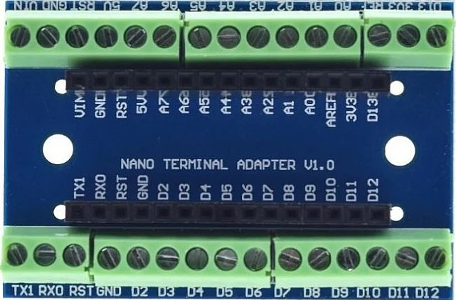
The Arduino NANO Terminal Adapter is an essential accessory designed to simplify the process of connecting the Arduino NANO microcontroller to various external components and circuits. By converting the NANO's small, surface-mounted pins to easy-to-use terminal blocks, this adapter makes prototyping and project construction more accessible and reliable.
Explore Projects Built with Arduino NANO terminal adapter
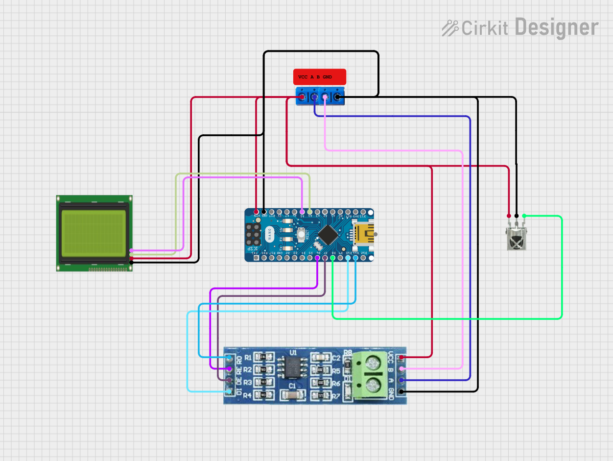

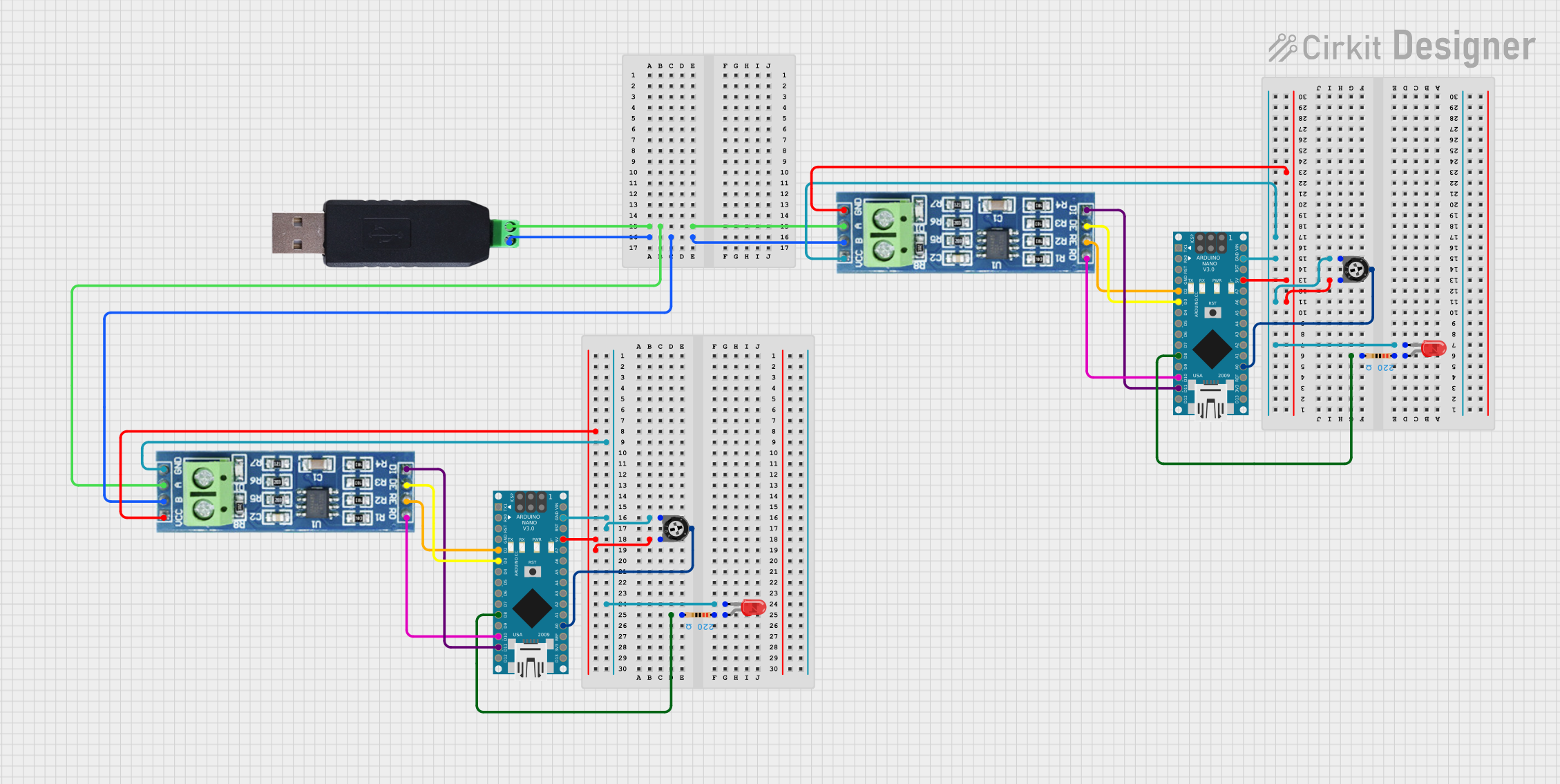
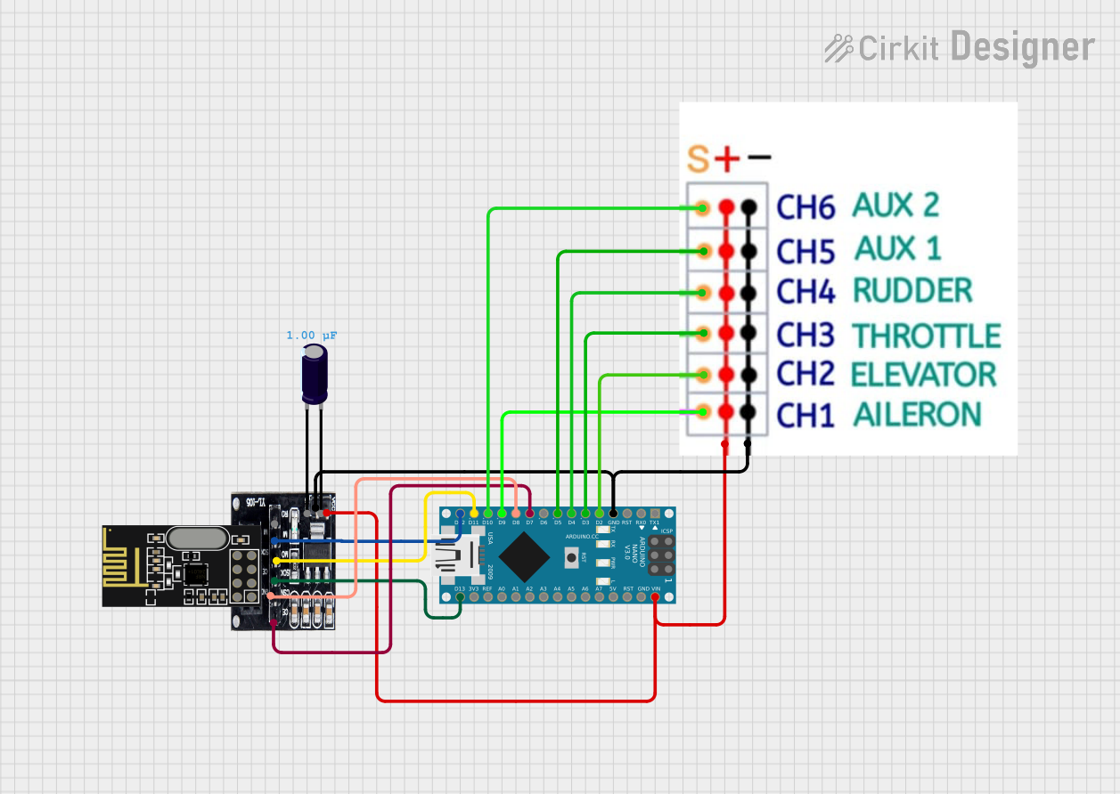
Explore Projects Built with Arduino NANO terminal adapter
Common Applications and Use Cases
- Rapid prototyping of electronic circuits
- Educational projects and learning environments
- Permanent installations in hobbyist projects
- Robotics and control systems
Technical Specifications
Key Technical Details
- Voltage Rating: Compatible with Arduino NANO operating voltage (5V)
- Current Rating: Dependent on terminal block specifications, typically around 1-2A
- Power Ratings: Follows Arduino NANO power specifications
Pin Configuration and Descriptions
| Pin Label | Description |
|---|---|
| D0-D13 | Digital pins 0 to 13, with PWM capability on certain pins |
| A0-A7 | Analog input pins 0 to 7 |
| 5V | 5V power supply from the Arduino NANO |
| 3V3 | 3.3V power supply from the Arduino NANO |
| GND | Ground connection |
| RST | Reset pin |
| VIN | Input voltage to the Arduino NANO |
| AREF | Analog reference voltage for the analog inputs |
Usage Instructions
How to Use the Component in a Circuit
- Inserting the Arduino NANO: Carefully align the pins of your Arduino NANO with the corresponding female headers on the terminal adapter and press gently to insert.
- Connecting External Components: Loosen the screws on the terminal blocks and insert the stripped end of a wire. Tighten the screw to secure the wire.
- Powering the Adapter: Ensure that the Arduino NANO is powered appropriately, either through the USB connection or the VIN pin if an external power supply is used.
Important Considerations and Best Practices
- Power Limits: Do not exceed the current rating of the terminal blocks to prevent damage.
- Signal Integrity: Keep wires as short as possible to minimize interference and signal degradation.
- Secure Connections: Always double-check that all connections are secure before powering up the circuit.
- Isolation: Be cautious when working with high voltages or currents; always isolate the Arduino NANO and adapter from these conditions.
Troubleshooting and FAQs
Common Issues Users Might Face
- Loose Connections: If the circuit is not working as expected, check all terminal block connections for looseness.
- Incorrect Wiring: Verify that all wires are connected to the correct terminal blocks according to the pin configuration.
Solutions and Tips for Troubleshooting
- Visual Inspection: Regularly inspect the adapter for any signs of damage or wear.
- Multimeter Checks: Use a multimeter to check for continuity and correct voltages at the terminal blocks.
- Firmware Verification: Ensure that the Arduino NANO is programmed with the correct firmware for your application.
FAQs
Q: Can I use the adapter with a power supply greater than 5V? A: The adapter itself does not regulate voltage; it passes through the voltage supplied to the VIN pin. The Arduino NANO can handle 6-20V on VIN, but it is recommended to use a regulated 5V or 7-12V to prevent overheating.
Q: Is soldering required to use this adapter? A: No, the adapter is designed for solderless connections using terminal blocks.
Q: Can I use this adapter with other Arduino boards? A: This adapter is specifically designed for the Arduino NANO form factor. It is not compatible with other Arduino boards without modification.
Example Code for Arduino UNO
// Blink an LED connected to the D13 terminal block on the adapter

void setup() {
  pinMode(13, OUTPUT); // Initialize digital pin 13 as an output.
}

void loop() {
  digitalWrite(13, HIGH); // Turn the LED on (HIGH is the voltage level)
  delay(1000);           // Wait for a second
  digitalWrite(13, LOW);  // Turn the LED off by making the voltage LOW
  delay(1000);           // Wait for a second
}
Note: The example code provided is for the Arduino UNO, which shares the same pinout as the Arduino NANO for the primary digital and analog pins. This code can be used directly on the Arduino NANO when using the terminal adapter.