
How to Use KIT_XMC14_2GO: Examples, Pinouts, and Specs
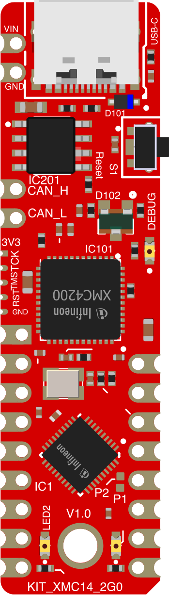
 Design with KIT_XMC14_2GO in Cirkit Designer
Introduction
The KIT_XMC14_2GO is a compact and versatile development board designed for the XMC microcontroller series, which is based on the ARM Cortex-M0 core. This board is ideal for rapid prototyping and development of embedded applications, offering easy access to a variety of peripherals and interfaces. Its small form factor and user-friendly design make it a popular choice for both hobbyists and professionals working on IoT, industrial automation, and other embedded systems.
Explore Projects Built with KIT_XMC14_2GO
 Open Project in Cirkit Designer
 Open Project in Cirkit Designer
 Open Project in Cirkit Designer
 Open Project in Cirkit Designer
Explore Projects Built with KIT_XMC14_2GO
Open Project in Cirkit DesignerOpen Project in Cirkit DesignerOpen Project in Cirkit DesignerOpen Project in Cirkit DesignerCommon Applications and Use Cases
- IoT device prototyping
- Motor control and industrial automation
- Sensor interfacing and data acquisition
- Low-power embedded systems
- Educational purposes for learning ARM Cortex-M0 programming
Technical Specifications
The following table outlines the key technical specifications of the KIT_XMC14_2GO:
| Specification | Details |
|---|---|
| Microcontroller | XMC1400 series (ARM Cortex-M0 core) |
| Operating Voltage | 3.3V |
| Input Voltage Range | 5V (via USB) |
| Clock Speed | Up to 48 MHz |
| Flash Memory | 64 KB |
| RAM | 16 KB |
| Communication Interfaces | UART, I2C, SPI, CAN |
| GPIO Pins | 11 (accessible via pin headers) |
| Debug Interface | On-board debugger (Segger J-Link OB) |
| Dimensions | 2.0 x 1.0 inches |
| Power Supply | USB-powered |
Pin Configuration and Descriptions
The KIT_XMC14_2GO provides access to the microcontroller's GPIO and peripheral pins through its headers. Below is the pin configuration:
| Pin Number | Pin Name | Function | Description |
|---|---|---|---|
| 1 | VDD | Power Supply | 3.3V output |
| 2 | GND | Ground | Common ground |
| 3 | P0.0 | GPIO / UART_TXD | General-purpose I/O or UART transmit |
| 4 | P0.1 | GPIO / UART_RXD | General-purpose I/O or UART receive |
| 5 | P0.2 | GPIO / I2C_SCL | General-purpose I/O or I2C clock line |
| 6 | P0.3 | GPIO / I2C_SDA | General-purpose I/O or I2C data line |
| 7 | P0.4 | GPIO / SPI_MOSI | General-purpose I/O or SPI master-out/slave-in |
| 8 | P0.5 | GPIO / SPI_MISO | General-purpose I/O or SPI master-in/slave-out |
| 9 | P0.6 | GPIO / SPI_SCK | General-purpose I/O or SPI clock |
| 10 | P0.7 | GPIO / CAN_TX | General-purpose I/O or CAN transmit |
| 11 | P0.8 | GPIO / CAN_RX | General-purpose I/O or CAN receive |
Usage Instructions
How to Use the KIT_XMC14_2GO in a Circuit
Powering the Board:
- Connect the KIT_XMC14_2GO to your computer or a USB power source using a micro-USB cable. The board operates at 3.3V internally but accepts 5V input via USB.
Programming the Microcontroller:
- Use the on-board Segger J-Link debugger to program the XMC1400 microcontroller. Compatible software includes Infineon's DAVE IDE or any ARM Cortex-M0 compatible development environment.
Connecting Peripherals:
- Use the GPIO pins to interface with external components such as sensors, actuators, or communication modules. Refer to the pin configuration table for specific pin functions.
Example Circuit:
- To blink an LED, connect the anode of the LED to a GPIO pin (e.g., P0.0) and the cathode to GND through a 220-ohm resistor.
Important Considerations and Best Practices
- Ensure that the total current drawn from the GPIO pins does not exceed the microcontroller's maximum current rating.
- Use level shifters if interfacing with 5V logic devices, as the KIT_XMC14_2GO operates at 3.3V.
- Avoid powering high-current devices directly from the board's GPIO pins; use external transistors or relays instead.
Example Code for Arduino UNO-Compatible Setup
Although the KIT_XMC14_2GO is not directly compatible with Arduino IDE, you can use the following pseudo-code to demonstrate basic functionality, such as blinking an LED:
// Example code to blink an LED connected to P0.0 on KIT_XMC14_2GO

#include <XMC_GPIO.h> // Include the XMC GPIO library

#define LED_PIN P0_0 // Define the GPIO pin for the LED

int main(void) {
    // Initialize the GPIO pin as output
    XMC_GPIO_SetMode(LED_PIN, XMC_GPIO_MODE_OUTPUT_PUSH_PULL);

    while (1) {
        // Turn the LED on
        XMC_GPIO_SetOutputHigh(LED_PIN);
        for (volatile int i = 0; i < 1000000; i++); // Delay loop

        // Turn the LED off
        XMC_GPIO_SetOutputLow(LED_PIN);
        for (volatile int i = 0; i < 1000000; i++); // Delay loop
    }

    return 0;
}
Troubleshooting and FAQs
Common Issues and Solutions
The board is not detected by the computer:
- Ensure the USB cable is properly connected and functional. Try using a different USB port or cable.
- Verify that the necessary drivers for the Segger J-Link debugger are installed.
Unable to program the microcontroller:
- Check that the DAVE IDE or your chosen development environment is correctly configured for the XMC1400 series.
- Ensure no other application is using the J-Link debugger.
GPIO pins are not functioning as expected:
- Double-check the pin configuration and ensure the correct mode (input/output) is set for each pin.
- Verify that the connected peripherals are compatible with the 3.3V logic level.
FAQs
Q: Can I use the KIT_XMC14_2GO with Arduino IDE?
A: No, the KIT_XMC14_2GO is not natively compatible with Arduino IDE. It is designed for use with Infineon's DAVE IDE or other ARM Cortex-M0 development tools.
Q: What is the maximum current output of the GPIO pins?
A: Each GPIO pin can source or sink up to 4 mA. For higher current requirements, use external drivers.
Q: Is the board suitable for low-power applications?
A: Yes, the XMC1400 microcontroller is optimized for low-power operation, making it suitable for battery-powered devices.