
How to Use BTS7960: Examples, Pinouts, and Specs
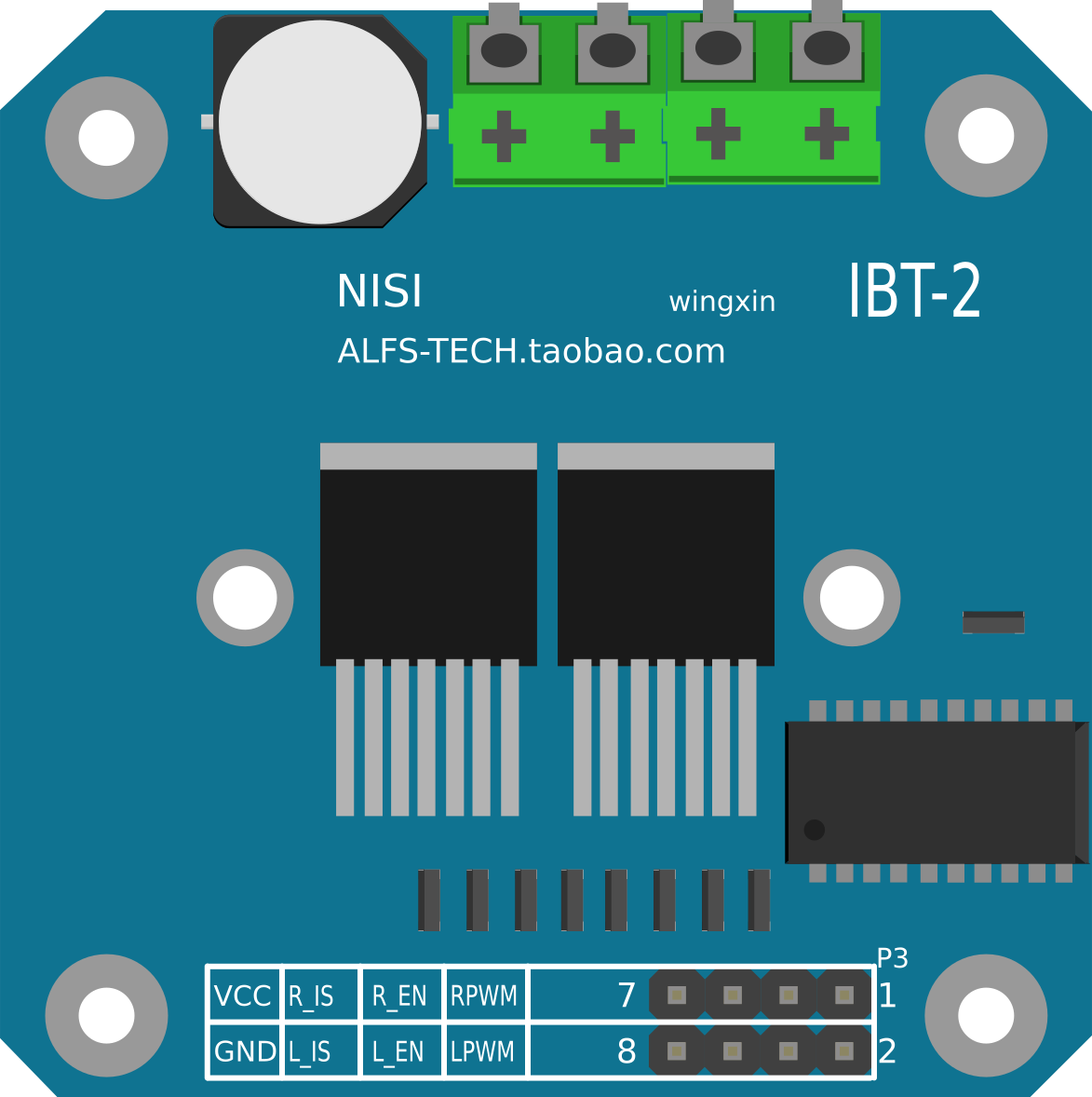
 Design with BTS7960 in Cirkit Designer
Introduction
The BTS7960 is a high-current H-bridge motor driver manufactured by Handson Technology (Part ID: BTS1790). It is designed to drive DC motors and other inductive loads with high efficiency and reliability. The BTS7960 integrates advanced protection features, including overcurrent, overtemperature, and undervoltage safeguards, making it ideal for demanding applications in robotics, industrial automation, and electric vehicles.
Explore Projects Built with BTS7960
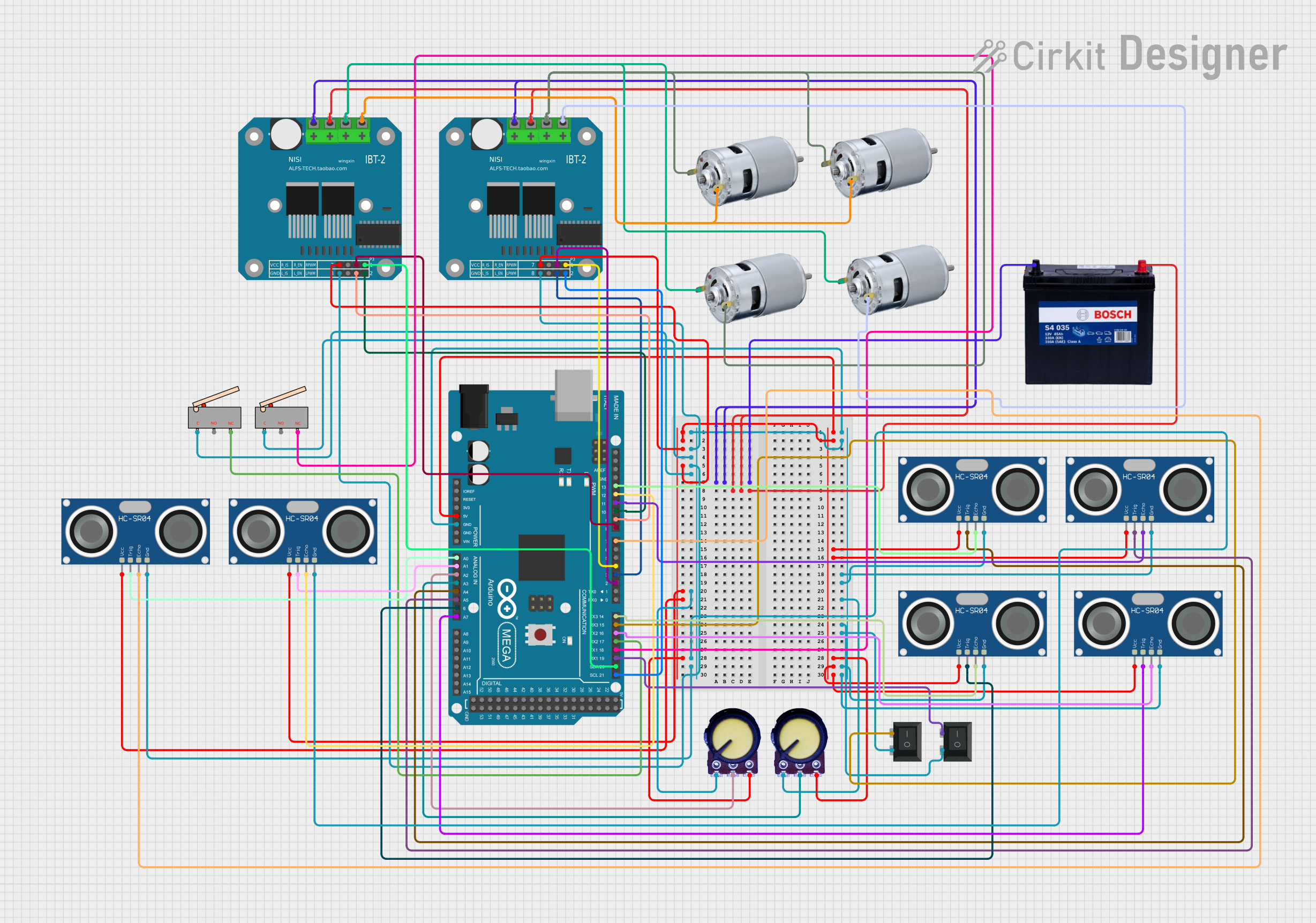 Open Project in Cirkit Designer
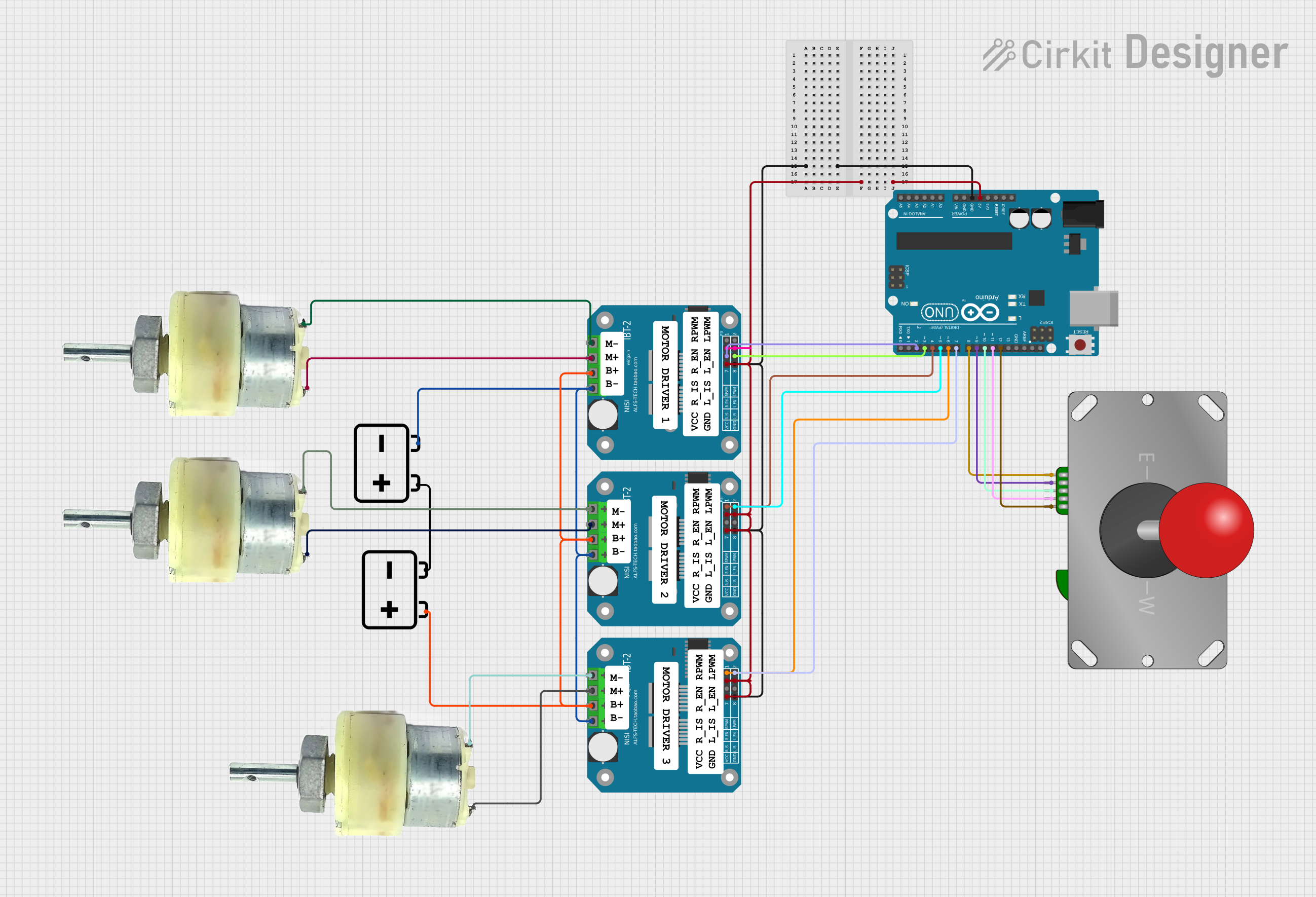 Open Project in Cirkit Designer
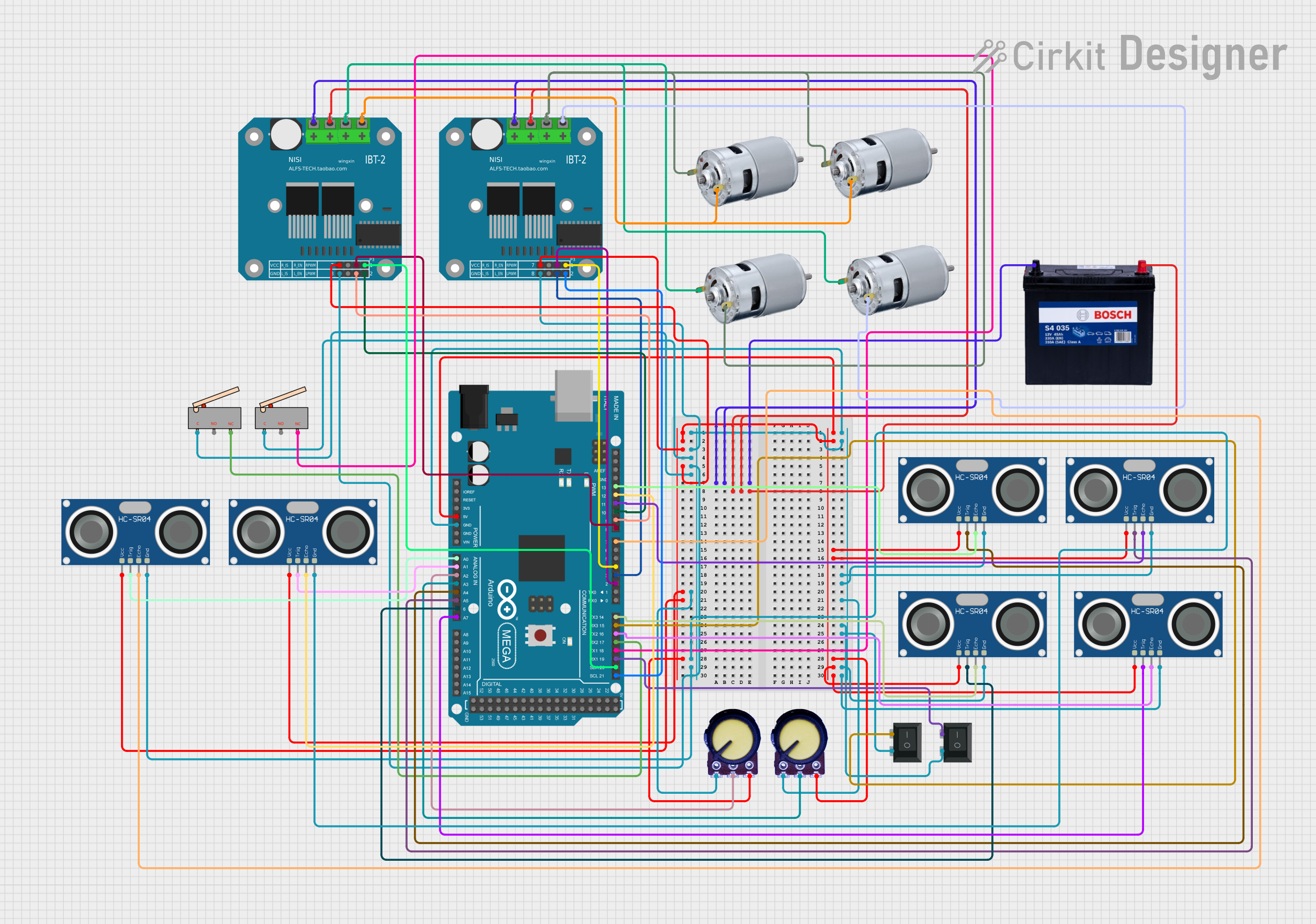 Open Project in Cirkit Designer
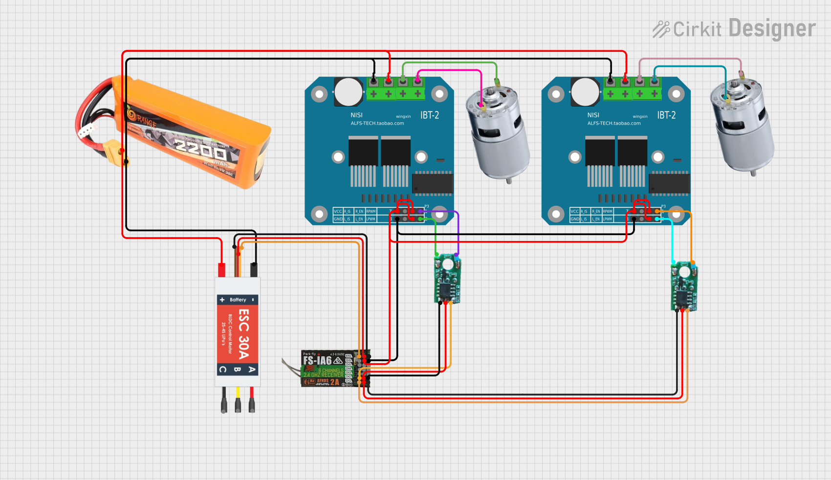 Open Project in Cirkit Designer
Explore Projects Built with BTS7960
Open Project in Cirkit DesignerOpen Project in Cirkit DesignerOpen Project in Cirkit DesignerOpen Project in Cirkit DesignerCommon Applications
- Robotics (e.g., motorized arms, wheeled robots)
- Industrial automation systems
- Electric vehicles and carts
- Conveyor belt systems
- High-power DC motor control
Technical Specifications
The BTS7960 is a robust motor driver with the following key specifications:
| Parameter | Value |
|---|---|
| Operating Voltage Range | 5.5V to 27V |
| Maximum Continuous Current | 43A |
| Peak Current (Short Duration) | 50A |
| PWM Frequency | Up to 25kHz |
| Logic Input Voltage | 3.3V or 5V (TTL compatible) |
| Overcurrent Protection | Yes |
| Overtemperature Protection | Yes |
| Undervoltage Lockout | Yes |
| Dimensions | 43mm x 43mm x 28mm |
Pin Configuration and Descriptions
The BTS7960 module typically comes with a 12-pin interface. Below is the pin configuration:
| Pin Name | Type | Description |
|---|---|---|
| VCC | Power Input | Connect to the motor power supply (5.5V to 27V). |
| GND | Power Ground | Ground connection for the motor power supply. |
| RPWM | Logic Input | PWM signal for controlling motor rotation in one direction. |
| LPWM | Logic Input | PWM signal for controlling motor rotation in the opposite direction. |
| R_EN | Logic Input | Enable pin for the right half-bridge. Set HIGH to enable. |
| L_EN | Logic Input | Enable pin for the left half-bridge. Set HIGH to enable. |
| IS | Analog Output | Current sensing output. Provides a voltage proportional to the motor current. |
| VCC5 | Power Input | Logic voltage input (3.3V or 5V). |
| BRAKE | Logic Input | Brake control pin. Set HIGH to activate braking. |
| MOTOR+ | Power Output | Connect to the positive terminal of the motor. |
| MOTOR- | Power Output | Connect to the negative terminal of the motor. |
| GND | Power Ground | Ground connection for the logic circuit. |
Usage Instructions
Connecting the BTS7960 to a Circuit
- Power Supply: Connect the motor power supply to the
VCCpin and ground to theGNDpin. Ensure the supply voltage is within the range of 5.5V to 27V. - Motor Connection: Attach the motor terminals to the
MOTOR+andMOTOR-pins. - Logic Inputs: Connect the control signals (
RPWM,LPWM,R_EN,L_EN, andBRAKE) to a microcontroller or other control circuitry. Ensure the logic voltage matches the microcontroller's output (3.3V or 5V). - Enable Pins: Set
R_ENandL_ENHIGH to enable the respective half-bridges. - PWM Control: Use the
RPWMandLPWMpins to control the motor's speed and direction via PWM signals.
Important Considerations
- Heat Dissipation: The BTS7960 can handle high currents, but it may generate significant heat. Use a heatsink or active cooling for prolonged high-current operation.
- Protection Features: The module includes built-in protection mechanisms. If the motor stops unexpectedly, check for overcurrent or overtemperature conditions.
- Current Sensing: The
ISpin provides a voltage proportional to the motor current. This can be used for monitoring or feedback control.
Example: Using BTS7960 with Arduino UNO
Below is an example of how to control a DC motor using the BTS7960 and an Arduino UNO:
// Define control pins for the BTS7960
#define RPWM 9    // PWM pin for forward rotation
#define LPWM 10   // PWM pin for reverse rotation
#define R_EN 7    // Enable pin for right half-bridge
#define L_EN 8    // Enable pin for left half-bridge

void setup() {
  // Set pin modes
  pinMode(RPWM, OUTPUT);
  pinMode(LPWM, OUTPUT);
  pinMode(R_EN, OUTPUT);
  pinMode(L_EN, OUTPUT);

  // Enable both half-bridges
  digitalWrite(R_EN, HIGH);
  digitalWrite(L_EN, HIGH);
}

void loop() {
  // Rotate motor forward at 50% speed
  analogWrite(RPWM, 128); // 50% duty cycle
  analogWrite(LPWM, 0);   // No reverse rotation
  delay(2000);            // Run for 2 seconds

  // Rotate motor in reverse at 75% speed
  analogWrite(RPWM, 0);   // No forward rotation
  analogWrite(LPWM, 192); // 75% duty cycle
  delay(2000);            // Run for 2 seconds

  // Stop the motor
  analogWrite(RPWM, 0);
  analogWrite(LPWM, 0);
  delay(2000);            // Wait for 2 seconds
}
Troubleshooting and FAQs
Common Issues
Motor Not Spinning
- Cause: Incorrect wiring or insufficient power supply.
- Solution: Double-check all connections and ensure the power supply voltage is within the specified range.
Overheating
- Cause: Prolonged high-current operation without proper cooling.
- Solution: Attach a heatsink or use active cooling (e.g., a fan).
PWM Signal Not Working
- Cause: Incorrect logic voltage or damaged microcontroller pins.
- Solution: Verify the logic voltage (3.3V or 5V) and test the microcontroller's PWM output.
Motor Vibrates but Does Not Rotate
- Cause: Conflicting signals on
RPWMandLPWMpins. - Solution: Ensure only one of the PWM pins is active at a time.
- Cause: Conflicting signals on
FAQs
Can the BTS7960 drive stepper motors?
- No, the BTS7960 is designed for DC motors and other inductive loads. For stepper motors, use a dedicated stepper motor driver.
What is the maximum PWM frequency supported?
- The BTS7960 supports PWM frequencies up to 25kHz.
Can I use the BTS7960 with a 3.3V microcontroller?
- Yes, the logic inputs are compatible with both 3.3V and 5V systems.
How do I implement braking?
- Set the
BRAKEpin HIGH to activate the braking function. This will short the motor terminals and stop the motor quickly.
- Set the
By following this documentation, users can effectively integrate the BTS7960 into their projects and troubleshoot common issues with ease.