How to Use Gravity LED button: Examples, Pinouts, and Specs
Introduction
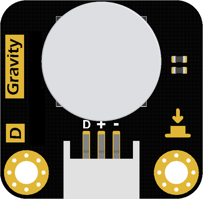
The Gravity LED Button (Manufacturer Part ID: DFR0785) by DFRobot is a versatile push-button switch that integrates an LED indicator. This component provides both tactile and visual feedback, making it ideal for interactive electronic projects. The LED illuminates when the button is pressed, offering a clear indication of the button's state. Its compact design and ease of use make it a popular choice for prototyping, DIY projects, and educational purposes.
Explore Projects Built with Gravity LED button


Explore Projects Built with Gravity LED button
Common Applications
- User input interfaces for microcontroller projects
- Status indication in control panels
- Interactive devices and games
- Educational kits for learning electronics
Technical Specifications
The following table outlines the key technical details of the Gravity LED Button:
| Parameter | Value |
|---|---|
| Operating Voltage | 3.3V to 5V |
| Operating Current | ≤ 20mA |
| Button Type | Momentary push-button |
| LED Color | Red |
| Connector Type | Gravity 3-pin interface |
| Dimensions | 22mm x 30mm x 13mm |
| Weight | 5g |
Pin Configuration
The Gravity LED Button features a 3-pin interface. The pinout is as follows:
| Pin | Label | Description |
|---|---|---|
| 1 | SIG |
Signal pin for button state (HIGH/LOW output) |
| 2 | VCC |
Power supply for the LED (3.3V or 5V) |
| 3 | GND |
Ground connection |
Usage Instructions
Connecting the Gravity LED Button
Wiring: Use the Gravity 3-pin cable to connect the button to your microcontroller or development board. Ensure the pins are connected as follows:
SIGto a digital input pin on the microcontroller.VCCto the 3.3V or 5V power supply (depending on your system).GNDto the ground pin.
Pull-up Resistor: The button typically requires an internal or external pull-up resistor to ensure stable operation. Most microcontrollers, such as the Arduino UNO, have built-in pull-up resistors that can be enabled in the code.
LED Behavior: The LED will light up when the button is pressed, providing visual feedback.
Example: Using with Arduino UNO
Below is an example code snippet to use the Gravity LED Button with an Arduino UNO. The code reads the button state and prints it to the Serial Monitor.
// Define the pin connections
const int buttonPin = 2; // Connect SIG to digital pin 2

void setup() {
  pinMode(buttonPin, INPUT_PULLUP); // Set button pin as input with pull-up resistor
  Serial.begin(9600);              // Initialize serial communication
}

void loop() {
  int buttonState = digitalRead(buttonPin); // Read the button state

  if (buttonState == LOW) {
    // Button is pressed (active LOW)
    Serial.println("Button Pressed");
  } else {
    // Button is not pressed
    Serial.println("Button Released");
  }

  delay(100); // Small delay to debounce the button
}
Best Practices
- Debouncing: Mechanical buttons may produce noise or "bouncing" when pressed. Use a small delay (e.g., 10-50ms) in your code or implement a software debouncing algorithm to ensure stable readings.
- Voltage Compatibility: Ensure the
VCCpin is connected to a voltage source within the specified range (3.3V to 5V) to avoid damaging the LED. - Secure Connections: Use the Gravity cable to ensure a reliable and secure connection to your microcontroller.
Troubleshooting and FAQs
Common Issues
LED Does Not Light Up
- Cause: Incorrect wiring or insufficient power supply.
- Solution: Double-check the connections, ensuring
VCCis connected to 3.3V or 5V andGNDis properly grounded.
Button State Not Detected
- Cause: The
SIGpin is not connected to the correct digital input pin or the pull-up resistor is not enabled. - Solution: Verify the
SIGpin connection and ensure the pull-up resistor is enabled in the code (INPUT_PULLUP).
- Cause: The
Unstable or Erratic Readings
- Cause: Button bouncing or electrical noise.
- Solution: Add a small delay in the code (e.g.,
delay(10)) or implement a software debouncing routine.
FAQs
Q: Can I use the Gravity LED Button with a 3.3V microcontroller?
A: Yes, the button is compatible with both 3.3V and 5V systems. Ensure the VCC pin is connected to the appropriate voltage source.
Q: Is the LED color customizable?
A: The default LED color is red. To use a different color, you would need to replace the internal LED, which may require advanced soldering skills.
Q: Can I use multiple buttons in a single project?
A: Yes, you can connect multiple buttons to different digital input pins on your microcontroller. Ensure each button has its own unique pin assignment.
Q: Does the button support latching behavior?
A: No, the Gravity LED Button is a momentary push-button, meaning it only remains active while pressed.
By following this documentation, you can effectively integrate the Gravity LED Button into your projects and troubleshoot any issues that arise.