Cirkit Designer Logo
Cirkit Designer
Your all-in-one circuit design IDE
Home / 
Component Documentation

How to Use accutaor: Examples, Pinouts, and Specs

Image of accutaor
Cirkit Designer LogoDesign with accutaor in Cirkit Designer

Introduction

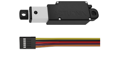
An actuator is a device that converts electrical energy into mechanical motion, enabling the control of a system or mechanism. Actuators are essential components in a wide range of applications, from industrial automation to robotics and consumer electronics. They are used to perform tasks such as opening valves, moving robotic arms, or adjusting the position of mechanical components.

Explore Projects Built with accutaor

Use Cirkit Designer to design, explore, and prototype these projects online. Some projects support real-time simulation. Click "Open Project" to start designing instantly!
Arduino UNO-Based Accident Detection and Alert System with GPS and GSM
Image of Circuit final: A project utilizing accutaor in a practical application
This circuit is an accident detection and alert system for a vehicle. It uses an Arduino UNO to interface with a GPS module, a GSM module, an accelerometer, and a motor driver to detect impacts, determine the vehicle's location, and send emergency alerts via SMS and calls. Additional components include a buzzer for audible alerts, a Bluetooth module for wireless communication, and an LED indicator.
Cirkit Designer LogoOpen Project in Cirkit Designer
Arduino UNO-Based Impact Detection and GPS Tracking System with GSM Communication
Image of smart helmet: A project utilizing accutaor in a practical application
This circuit features an Arduino UNO interfaced with an ADXXL335 accelerometer, a Neo 6M GPS module, and a Sim800l GSM module. The Arduino collects acceleration data and GPS coordinates, and can send SMS alerts or make calls via the GSM module in case of a detected impact or upon receiving a specific SMS command. The system is designed for applications such as vehicle tracking and accident detection.
Cirkit Designer LogoOpen Project in Cirkit Designer
Arduino-Based Accident Detection System with GPS and GSM
Image of EL Circuit: A project utilizing accutaor in a practical application
This circuit is an accident detection system that uses an Arduino UNO to monitor an accelerometer for collision detection. Upon detecting a collision, it activates a buzzer, retrieves GPS coordinates, displays them on an LCD, and uses a GSM module to call and send an emergency message with the location.
Cirkit Designer LogoOpen Project in Cirkit Designer
Arduino UNO-Based Sensor Monitoring and GSM Communication System
Image of pot new: A project utilizing accutaor in a practical application
This is a multifunctional Arduino-based system designed to interface with an ultrasonic sensor for distance measurement, an IR sensor for object detection, a GPS module for location tracking, a GSM module for cellular communication, an I2C LCD display for user interface, and an OV7670 camera module for image capture. The Arduino manages sensor data processing and module communication, indicating a complex application such as a security or surveillance device with remote reporting capabilities.
Cirkit Designer LogoOpen Project in Cirkit Designer

Explore Projects Built with accutaor

Use Cirkit Designer to design, explore, and prototype these projects online. Some projects support real-time simulation. Click "Open Project" to start designing instantly!
Image of Circuit final: A project utilizing accutaor in a practical application
Arduino UNO-Based Accident Detection and Alert System with GPS and GSM
This circuit is an accident detection and alert system for a vehicle. It uses an Arduino UNO to interface with a GPS module, a GSM module, an accelerometer, and a motor driver to detect impacts, determine the vehicle's location, and send emergency alerts via SMS and calls. Additional components include a buzzer for audible alerts, a Bluetooth module for wireless communication, and an LED indicator.
Cirkit Designer LogoOpen Project in Cirkit Designer
Image of smart helmet: A project utilizing accutaor in a practical application
Arduino UNO-Based Impact Detection and GPS Tracking System with GSM Communication
This circuit features an Arduino UNO interfaced with an ADXXL335 accelerometer, a Neo 6M GPS module, and a Sim800l GSM module. The Arduino collects acceleration data and GPS coordinates, and can send SMS alerts or make calls via the GSM module in case of a detected impact or upon receiving a specific SMS command. The system is designed for applications such as vehicle tracking and accident detection.
Cirkit Designer LogoOpen Project in Cirkit Designer
Image of EL Circuit: A project utilizing accutaor in a practical application
Arduino-Based Accident Detection System with GPS and GSM
This circuit is an accident detection system that uses an Arduino UNO to monitor an accelerometer for collision detection. Upon detecting a collision, it activates a buzzer, retrieves GPS coordinates, displays them on an LCD, and uses a GSM module to call and send an emergency message with the location.
Cirkit Designer LogoOpen Project in Cirkit Designer
Image of pot new: A project utilizing accutaor in a practical application
Arduino UNO-Based Sensor Monitoring and GSM Communication System
This is a multifunctional Arduino-based system designed to interface with an ultrasonic sensor for distance measurement, an IR sensor for object detection, a GPS module for location tracking, a GSM module for cellular communication, an I2C LCD display for user interface, and an OV7670 camera module for image capture. The Arduino manages sensor data processing and module communication, indicating a complex application such as a security or surveillance device with remote reporting capabilities.
Cirkit Designer LogoOpen Project in Cirkit Designer

Common Applications and Use Cases

  • Industrial Automation: Controlling machinery, conveyor belts, and robotic arms.
  • Robotics: Enabling movement in robotic joints and grippers.
  • Automotive Systems: Powering components like electric windows, seats, and throttle control.
  • Home Automation: Operating smart locks, motorized blinds, and HVAC systems.
  • Medical Devices: Adjusting surgical instruments or prosthetics.

Technical Specifications

Actuators come in various types, such as electric, hydraulic, and pneumatic. Below are the general technical specifications for an electric actuator:

General Specifications

Parameter Value/Range
Operating Voltage 5V to 24V DC (varies by model)
Current Consumption 100mA to 5A (depending on load)
Torque Output 0.1 Nm to 50 Nm
Stroke Length 10mm to 300mm
Speed 5mm/s to 100mm/s
Operating Temperature -20°C to 60°C
Control Signal PWM, Analog, or Digital Input

Pin Configuration and Descriptions

The pin configuration for a typical 2-wire or 3-wire electric actuator is as follows:

2-Wire Actuator

Pin Name Description
V+ Positive voltage input (power supply)
GND Ground connection

3-Wire Actuator

Pin Name Description
V+ Positive voltage input (power supply)
GND Ground connection
Signal Control signal input (PWM or analog)

Usage Instructions

How to Use the Component in a Circuit

  1. Power Supply: Connect the actuator's V+ pin to a suitable DC power source and the GND pin to ground.
  2. Control Signal: For actuators with a signal pin, connect it to a microcontroller (e.g., Arduino UNO) or a control circuit capable of generating the required PWM or analog signal.
  3. Load Considerations: Ensure the actuator's torque and speed ratings match the requirements of your application.
  4. Protection: Use a flyback diode across the actuator terminals to protect against voltage spikes caused by inductive loads.

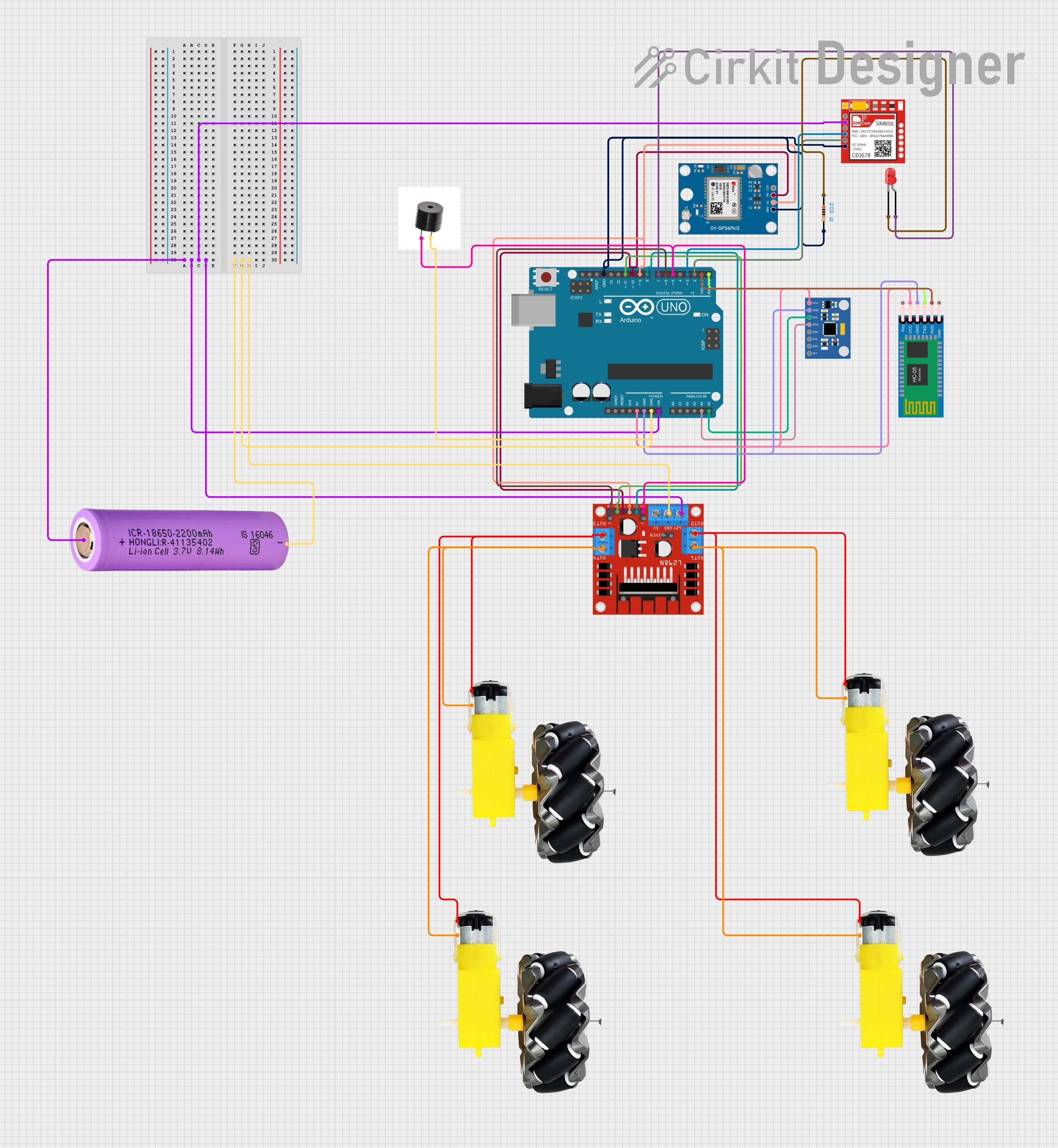
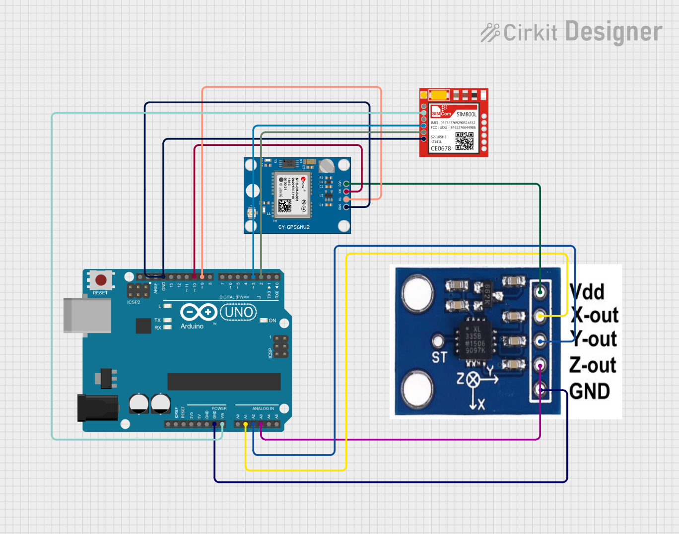
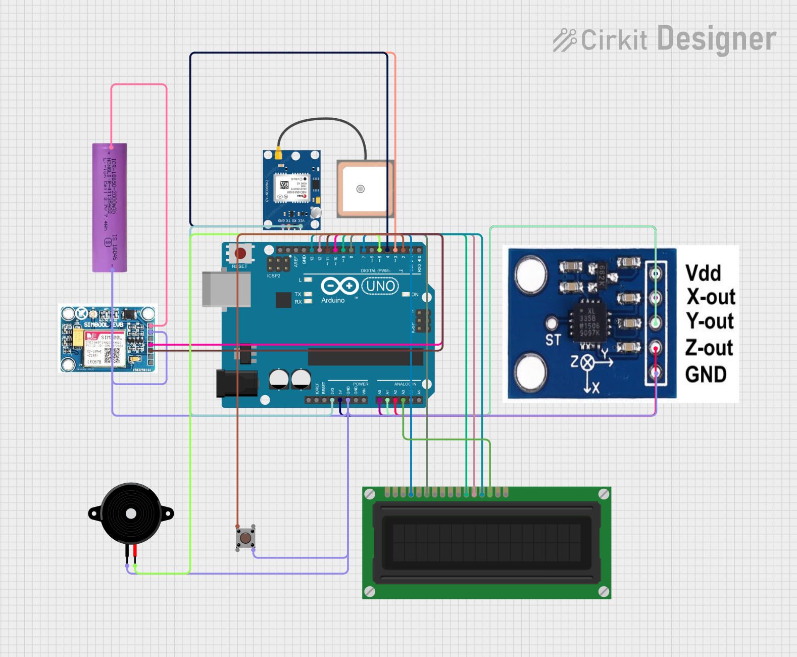
Example: Connecting an Actuator to an Arduino UNO

Below is an example of controlling a 3-wire actuator using an Arduino UNO and a PWM signal:

// Define the pin connected to the actuator's signal input
const int actuatorPin = 9;

void setup() {
  // Set the actuator pin as an output
  pinMode(actuatorPin, OUTPUT);
}

void loop() {
  // Extend the actuator by sending a PWM signal
  analogWrite(actuatorPin, 255); // Full speed forward
  delay(2000); // Wait for 2 seconds

  // Stop the actuator
  analogWrite(actuatorPin, 0); // No movement
  delay(1000); // Wait for 1 second

  // Retract the actuator by sending a lower PWM signal
  analogWrite(actuatorPin, 128); // Half speed reverse
  delay(2000); // Wait for 2 seconds

  // Stop the actuator
  analogWrite(actuatorPin, 0); // No movement
  delay(1000); // Wait for 1 second
}

Important Considerations and Best Practices

  • Power Supply: Ensure the power supply can provide sufficient current for the actuator under load.
  • Signal Compatibility: Verify that the control signal (PWM or analog) matches the actuator's requirements.
  • Mechanical Limits: Avoid exceeding the actuator's stroke length or torque limits to prevent damage.
  • Heat Dissipation: Allow adequate ventilation to prevent overheating during prolonged operation.

Troubleshooting and FAQs

Common Issues and Solutions

  1. Actuator Does Not Move

    • Cause: Insufficient power supply or incorrect wiring.
    • Solution: Check the power supply voltage and current ratings. Verify all connections.
  2. Erratic or Unstable Movement

    • Cause: Noise in the control signal or insufficient grounding.
    • Solution: Use shielded cables for the signal line and ensure a solid ground connection.
  3. Overheating

    • Cause: Prolonged operation under heavy load or inadequate ventilation.
    • Solution: Reduce the load or provide better cooling.
  4. Actuator Stuck at Full Extension/Retraction

    • Cause: Mechanical obstruction or exceeded stroke limit.
    • Solution: Inspect for obstructions and ensure the actuator is within its rated stroke length.

FAQs

Q: Can I use an actuator with an AC power supply?
A: Most actuators are designed for DC power. If you need to use AC, ensure the actuator is compatible or use a DC power adapter.

Q: How do I control the speed of an actuator?
A: The speed can be controlled by varying the PWM duty cycle or using a motor driver circuit.

Q: Can I connect multiple actuators to a single microcontroller?
A: Yes, but ensure the microcontroller has enough PWM pins and the power supply can handle the combined current draw.

Q: What happens if I exceed the actuator's torque rating?
A: Exceeding the torque rating can damage the actuator's internal components or cause it to stall.

This documentation provides a comprehensive guide to understanding and using actuators effectively in various applications.