How to Use Adafruit Feather RP2040 CAN Bus: Examples, Pinouts, and Specs
Adafruit Feather RP2040 CAN Bus (Part ID: 5724)
Introduction
The Adafruit Feather RP2040 CAN Bus is a compact and versatile microcontroller board designed for robust communication in automotive, industrial, and IoT applications. Powered by the Raspberry Pi RP2040 chip, this board integrates CAN Bus capabilities, making it ideal for projects requiring reliable communication between devices in a network. Its small form factor and compatibility with the Feather ecosystem make it a powerful tool for developers and hobbyists alike.
Common Applications
- Automotive systems (e.g., ECU communication, diagnostics)
- Industrial automation and control
- IoT devices requiring CAN Bus communication
- Robotics and sensor networks
- Data logging and telemetry systems
Technical Specifications
The following table outlines the key technical details of the Adafruit Feather RP2040 CAN Bus:
| Parameter | Specification |
|---|---|
| Microcontroller | Raspberry Pi RP2040 (Dual-core ARM Cortex-M0+ @ 133 MHz) |
| Flash Memory | 8 MB QSPI Flash |
| RAM | 264 KB SRAM |
| CAN Bus Controller | MCP2515 with MCP2562 CAN transceiver |
| Operating Voltage | 3.3V logic level |
| Input Voltage | 3.3V to 6V (via USB-C or LiPo battery) |
| Connectivity | CAN Bus, I2C, SPI, UART |
| GPIO Pins | 21 GPIO pins (3.3V logic) |
| Power Options | USB-C, LiPo battery (with built-in charging circuit) |
| Dimensions | 51mm x 23mm x 8mm |
| Weight | 5.5g |
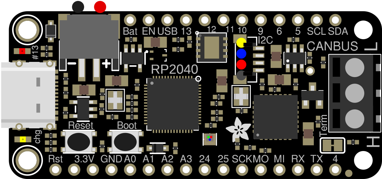
Pin Configuration
The Adafruit Feather RP2040 CAN Bus features a standard Feather pinout. Below is the pin configuration:
| Pin | Name | Description |
|---|---|---|
| 1 | USB | USB-C connector for power and programming |
| 2 | BAT | LiPo battery input |
| 3 | 3V3 | 3.3V output |
| 4 | GND | Ground |
| 5 | A0-A5 | Analog input pins (3.3V max) |
| 6 | D0-D13 | Digital I/O pins (3.3V logic) |
| 7 | SCL/SDA | I2C communication pins |
| 8 | RX/TX | UART communication pins |
| 9 | CANH/CANL | CAN Bus high and low lines |
| 10 | EN | Enable pin to turn the board on/off |
| 11 | RST | Reset pin |
Usage Instructions
Getting Started
Powering the Board:
- Connect the board to your computer via the USB-C port for power and programming.
- Alternatively, use a 3.7V LiPo battery for portable applications.
Installing Software:
- Download and install the latest version of the Arduino IDE or CircuitPython.
- Install the necessary libraries for CAN Bus communication (e.g.,
Adafruit_MCP2515).
Connecting to a CAN Bus Network:
- Use the CANH and CANL pins to connect the board to the CAN Bus network.
- Ensure proper termination resistors (typically 120Ω) are present at both ends of the CAN Bus.
Example Circuit
Below is a simple example of connecting the Adafruit Feather RP2040 CAN Bus to a CAN Bus network:
+-------------------+       +-------------------+
| Feather RP2040    |       | CAN Bus Device    |
|                   |       |                   |
| CANH ------------ CANH    CANH ------------ CANH
| CANL ------------ CANL    CANL ------------ CANL
+-------------------+       +-------------------+
Example Code
The following Arduino sketch demonstrates how to send and receive messages on the CAN Bus using the Adafruit Feather RP2040 CAN Bus:
#include <Adafruit_MCP2515.h>

// Create an MCP2515 instance for CAN Bus communication
Adafruit_MCP2515 CAN;

// Define a CAN message object
struct CANMessage {
  uint32_t id;       // Message ID
  uint8_t data[8];   // Data payload (up to 8 bytes)
  uint8_t length;    // Length of the data payload
};

void setup() {
  Serial.begin(115200); // Initialize serial communication for debugging
  while (!Serial);

  // Initialize the CAN Bus at 500 kbps
  if (!CAN.begin(500000)) {
    Serial.println("Failed to initialize CAN Bus!");
    while (1);
  }
  Serial.println("CAN Bus initialized successfully.");
}

void loop() {
  // Create a message to send
  CANMessage message;
  message.id = 0x123;          // Set the message ID
  message.length = 2;          // Set the data length
  message.data[0] = 0xAB;      // First byte of data
  message.data[1] = 0xCD;      // Second byte of data

  // Send the message
  if (CAN.sendMessage(&message)) {
    Serial.println("Message sent successfully!");
  } else {
    Serial.println("Failed to send message.");
  }

  delay(1000); // Wait 1 second before sending the next message
}
Important Considerations
- Voltage Levels: Ensure all connected devices operate at 3.3V logic levels to avoid damage.
- Termination Resistors: Proper termination is critical for reliable CAN Bus communication.
- Library Compatibility: Use the latest versions of the Adafruit libraries for optimal performance.
Troubleshooting and FAQs
Common Issues
CAN Bus Communication Fails:
- Solution: Verify the wiring of CANH and CANL. Ensure proper termination resistors are in place.
Board Not Recognized by Computer:
- Solution: Check the USB-C cable and port. Ensure the board is in bootloader mode if necessary.
Message Not Sent or Received:
- Solution: Confirm the CAN Bus speed matches across all devices. Check for conflicts in message IDs.
FAQs
Q: Can I use this board with CircuitPython?
A: Yes, the Adafruit Feather RP2040 CAN Bus is fully compatible with CircuitPython. Install the necessary libraries from the Adafruit CircuitPython bundle.
Q: What is the maximum CAN Bus speed supported?
A: The MCP2515 controller supports speeds up to 1 Mbps.
Q: Can I power the board with a LiPo battery?
A: Yes, the board includes a built-in charging circuit for 3.7V LiPo batteries.
Additional Resources
- Adafruit Feather RP2040 CAN Bus Product Page
- Adafruit MCP2515 Library Documentation
- RP2040 Datasheet
This documentation provides a comprehensive guide to using the Adafruit Feather RP2040 CAN Bus. Whether you're a beginner or an experienced developer, this board offers a powerful platform for your next CAN Bus project.
Explore Projects Built with Adafruit Feather RP2040 CAN Bus
Explore Projects Built with Adafruit Feather RP2040 CAN Bus