How to Use ESP32 (38 pins): Examples, Pinouts, and Specs
Introduction
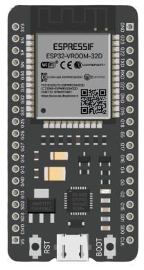
The ESP32 is a powerful microcontroller with integrated Wi-Fi and Bluetooth capabilities, making it an ideal choice for Internet of Things (IoT) applications and embedded systems. With its 38 pins, the ESP32 offers a wide range of input/output (I/O) functions, including digital and analog pins, PWM, I2C, SPI, UART, and more. Its dual-core processor and low-power modes make it suitable for both high-performance and energy-efficient applications.
Explore Projects Built with ESP32 (38 pins)

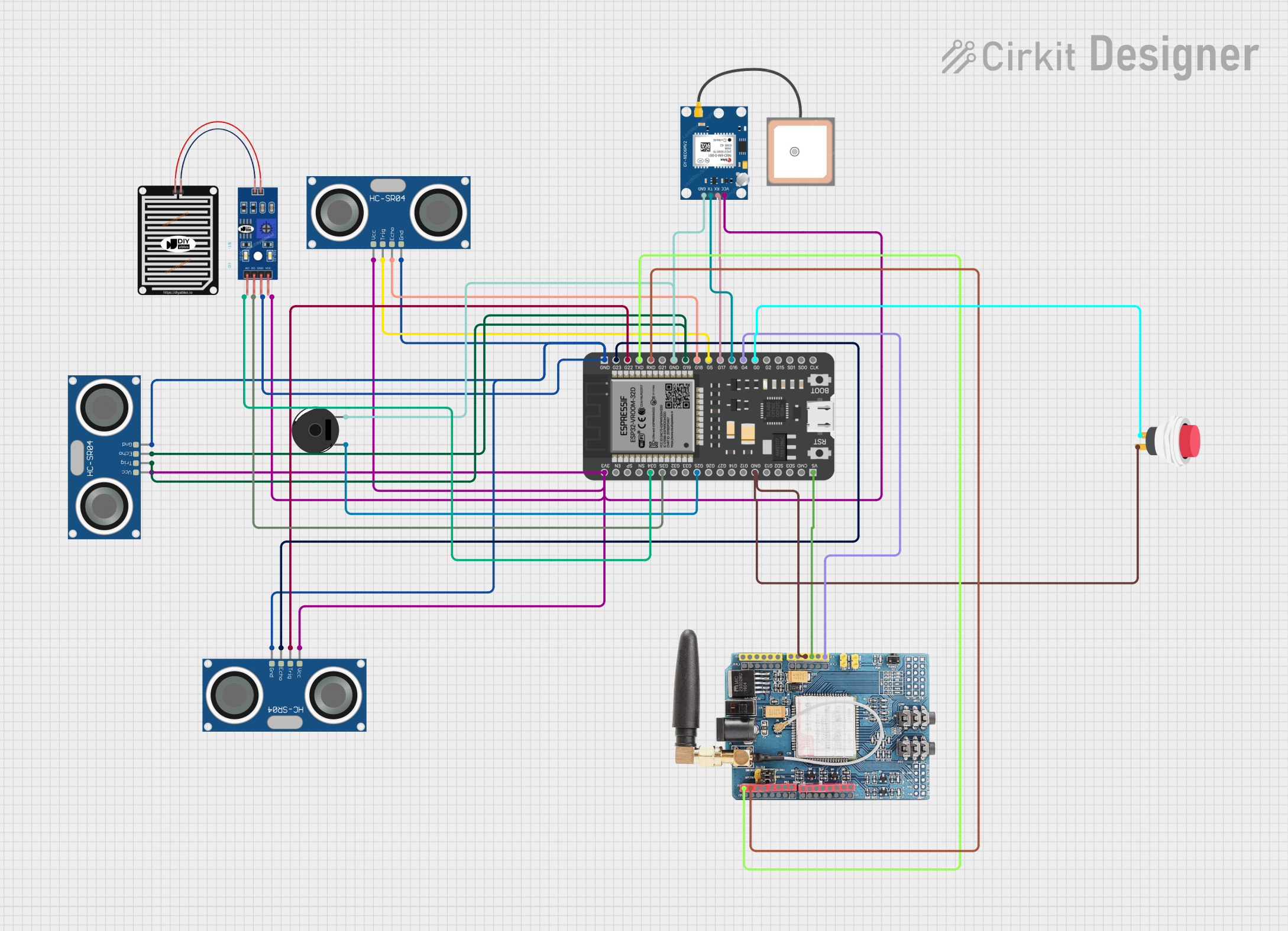

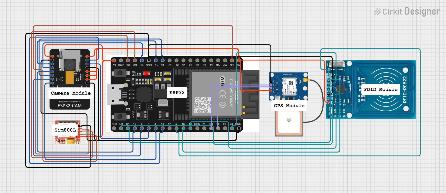
Explore Projects Built with ESP32 (38 pins)
Common Applications and Use Cases
- IoT devices (e.g., smart home systems, wearables, and sensors)
- Wireless communication (Wi-Fi and Bluetooth)
- Robotics and automation
- Data logging and remote monitoring
- Prototyping and development of embedded systems
Technical Specifications
The ESP32 (38 pins) is packed with features that make it versatile and powerful. Below are its key technical specifications:
Key Technical Details
- Processor: Dual-core Xtensa® 32-bit LX6 microprocessor
- Clock Speed: Up to 240 MHz
- Flash Memory: 4 MB (varies by model)
- SRAM: 520 KB
- Wi-Fi: 802.11 b/g/n
- Bluetooth: v4.2 BR/EDR and BLE
- Operating Voltage: 3.3V
- Input Voltage Range: 5V (via USB) or 3.3V (via VIN pin)
- GPIO Pins: 34 (configurable as digital I/O, PWM, ADC, etc.)
- ADC Channels: 18 (12-bit resolution)
- DAC Channels: 2 (8-bit resolution)
- Communication Protocols: UART, SPI, I2C, I2S, CAN
- Power Modes: Active, Light Sleep, Deep Sleep, Hibernation
- Operating Temperature: -40°C to +85°C
Pin Configuration and Descriptions
The ESP32 (38 pins) has a variety of pins for different functionalities. Below is a table summarizing the pin configuration:
| Pin Name | Function | Description |
|---|---|---|
| VIN | Power Input | Input voltage (5V) for powering the ESP32 via an external source. |
| GND | Ground | Ground connection. |
| 3V3 | Power Output | Provides 3.3V output for external components. |
| GPIO0 | Digital I/O, Boot Mode Selection | Used for boot mode selection during programming. |
| GPIO1 (TX0) | UART TX | UART0 transmit pin. |
| GPIO3 (RX0) | UART RX | UART0 receive pin. |
| GPIO2 | Digital I/O, ADC, PWM | General-purpose I/O, ADC, or PWM output. |
| GPIO4 | Digital I/O, ADC, PWM | General-purpose I/O, ADC, or PWM output. |
| GPIO5 | Digital I/O, ADC, PWM, SPI | General-purpose I/O or SPI clock. |
| GPIO12-15 | Digital I/O, ADC, PWM, Touch | Configurable as touch sensors, ADC, or PWM outputs. |
| GPIO16-19 | Digital I/O, SPI, I2C | Configurable for SPI or I2C communication. |
| GPIO21-23 | Digital I/O, I2C, PWM | Configurable for I2C communication or PWM outputs. |
| GPIO25-27 | Digital I/O, ADC, DAC, PWM | Includes DAC channels for analog output. |
| GPIO32-39 | Digital I/O, ADC, Touch | Configurable as touch sensors or ADC inputs. |
| EN | Enable | Resets the chip when pulled low. |
| BOOT | Boot Mode Selection | Used for flashing firmware. |
Note: Not all GPIO pins support all functions simultaneously. Refer to the ESP32 datasheet for pin multiplexing details.
Usage Instructions
How to Use the ESP32 in a Circuit
Powering the ESP32:
- Use the VIN pin to supply 5V from an external power source, or connect the ESP32 to a computer via a USB cable.
- Ensure the power supply is stable and within the recommended voltage range.
Connecting Peripherals:
- Use GPIO pins for digital I/O, ADC, PWM, or communication protocols (e.g., I2C, SPI, UART).
- For analog input, connect sensors to ADC-capable pins (e.g., GPIO32-39).
- For analog output, use DAC-capable pins (e.g., GPIO25-26).
Programming the ESP32:
- Install the Arduino IDE and add the ESP32 board package.
- Connect the ESP32 to your computer via USB.
- Select the correct board and port in the Arduino IDE.
- Write and upload your code.
Example Code: Blinking an LED
The following example demonstrates how to blink an LED connected to GPIO2:
// Define the GPIO pin where the LED is connected
const int ledPin = 2;

void setup() {
  // Set the LED pin as an output
  pinMode(ledPin, OUTPUT);
}

void loop() {
  // Turn the LED on
  digitalWrite(ledPin, HIGH);
  delay(1000); // Wait for 1 second

  // Turn the LED off
  digitalWrite(ledPin, LOW);
  delay(1000); // Wait for 1 second
}
Important Considerations and Best Practices
- Voltage Levels: The ESP32 operates at 3.3V logic levels. Avoid connecting 5V signals directly to GPIO pins.
- Boot Mode: Ensure GPIO0 is pulled low during programming to enter boot mode.
- Power Supply: Use a stable power source to avoid unexpected resets or malfunctions.
- Pin Multiplexing: Be aware of pin multiplexing to avoid conflicts between peripherals.
Troubleshooting and FAQs
Common Issues and Solutions
ESP32 Not Detected by Computer:
- Ensure the USB cable is functional and supports data transfer.
- Install the correct USB-to-serial driver for your operating system.
Upload Fails with "Failed to Connect" Error:
- Hold the BOOT button while uploading the code.
- Check the USB connection and ensure the correct port is selected in the Arduino IDE.
Random Resets or Instability:
- Verify that the power supply is stable and provides sufficient current (at least 500mA).
- Avoid using GPIO pins connected to peripherals during boot (e.g., GPIO0, GPIO2).
Wi-Fi Connection Issues:
- Double-check the SSID and password in your code.
- Ensure the router is within range and supports 2.4 GHz Wi-Fi.
FAQs
Q: Can I use the ESP32 with a 5V sensor?
A: Yes, but you need a voltage divider or level shifter to step down the 5V signal to 3.3V.
Q: How do I reduce power consumption?
A: Use the ESP32's deep sleep or hibernation modes to minimize power usage during idle periods.
Q: Can I use the ESP32 for Bluetooth and Wi-Fi simultaneously?
A: Yes, the ESP32 supports simultaneous use of Bluetooth and Wi-Fi, but performance may vary depending on the application.
Q: What is the maximum current output of GPIO pins?
A: Each GPIO pin can source or sink up to 12mA. Avoid exceeding this limit to prevent damage.
By following this documentation, you can effectively use the ESP32 (38 pins) for a wide range of applications.