How to Use ESP32-S3 Breakout board: Examples, Pinouts, and Specs
Introduction
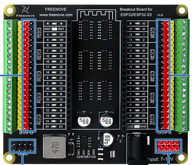
The ESP32-S3 Breakout Board (Manufacturer: Freenove, Part ID: FNK0091) is a versatile development board featuring the ESP32-S3 microcontroller. This microcontroller is equipped with dual-core Xtensa LX7 processors, integrated Wi-Fi (802.11 b/g/n), and Bluetooth 5.0 LE capabilities, making it ideal for IoT, smart devices, and wireless communication projects. The board is designed for rapid prototyping and supports a wide range of peripherals and sensors.
Explore Projects Built with ESP32-S3 Breakout board


Explore Projects Built with ESP32-S3 Breakout board
Common Applications and Use Cases
- IoT devices and smart home automation
- Wireless communication and networking
- Wearable technology
- Robotics and sensor integration
- Edge computing and AI/ML applications
Technical Specifications
The following table outlines the key technical details of the ESP32-S3 Breakout Board:
| Parameter | Specification |
|---|---|
| Microcontroller | ESP32-S3 (Xtensa LX7 dual-core, 240 MHz) |
| Flash Memory | 8 MB (external) |
| PSRAM | 8 MB |
| Wi-Fi | 802.11 b/g/n (2.4 GHz) |
| Bluetooth | Bluetooth 5.0 LE |
| GPIO Pins | 25 (configurable for digital, analog, I2C, SPI, etc.) |
| Operating Voltage | 3.3V |
| Input Voltage Range | 5V (via USB-C) or 3.3V (via pin headers) |
| USB Interface | USB-C (for power, programming, and debugging) |
| Dimensions | 54 mm x 25 mm |
| Power Consumption | ~10 µA in deep sleep mode |
Pin Configuration and Descriptions
The ESP32-S3 Breakout Board features a standard pinout for easy integration. Below is the pin configuration:
| Pin | Name | Description |
|---|---|---|
| 1 | GND | Ground |
| 2 | 3V3 | 3.3V power output |
| 3 | EN | Enable pin (active high) |
| 4 | IO0 | GPIO0, boot mode selection |
| 5 | IO1 | GPIO1, UART TX |
| 6 | IO2 | GPIO2, general-purpose I/O |
| 7 | IO3 | GPIO3, UART RX |
| 8 | IO4 | GPIO4, PWM capable |
| 9 | IO5 | GPIO5, SPI SCK |
| 10 | IO12 | GPIO12, ADC capable |
| 11 | IO13 | GPIO13, I2C SDA |
| 12 | IO14 | GPIO14, I2C SCL |
| 13 | IO15 | GPIO15, SPI MOSI |
| 14 | IO16 | GPIO16, SPI MISO |
| 15 | IO17 | GPIO17, UART CTS |
| 16 | IO18 | GPIO18, UART RTS |
| 17 | VIN | Input voltage (5V) |
Usage Instructions
How to Use the ESP32-S3 Breakout Board in a Circuit
Powering the Board:
- Connect the board to a USB-C cable for power and programming.
- Alternatively, supply 3.3V to the
3V3pin or 5V to theVINpin.
Programming the Board:
- Install the Arduino IDE or ESP-IDF (Espressif IoT Development Framework).
- Add the ESP32-S3 board support package to your development environment.
- Connect the board to your computer via USB-C and select the appropriate COM port.
Connecting Peripherals:
- Use the GPIO pins to connect sensors, actuators, or other peripherals.
- Configure the pins in your code for digital, analog, I2C, SPI, or UART functionality.
Uploading Code:
- Write your program in the Arduino IDE or ESP-IDF.
- Click the upload button to flash the code to the ESP32-S3.
Important Considerations and Best Practices
- Voltage Levels: Ensure all connected peripherals operate at 3.3V logic levels to avoid damaging the board.
- Deep Sleep Mode: Use deep sleep mode to minimize power consumption in battery-powered applications.
- Boot Mode: Hold the
IO0pin low during reset to enter bootloader mode for firmware updates. - Pin Multiplexing: Be aware that some pins have multiple functions (e.g., ADC, I2C, SPI). Configure them appropriately in your code.
Example Code for Arduino IDE
Below is an example of how to blink an LED connected to GPIO4:
// Define the GPIO pin for the LED
#define LED_PIN 4

void setup() {
  // Initialize the LED pin as an output
  pinMode(LED_PIN, OUTPUT);
}

void loop() {
  // Turn the LED on
  digitalWrite(LED_PIN, HIGH);
  delay(1000); // Wait for 1 second

  // Turn the LED off
  digitalWrite(LED_PIN, LOW);
  delay(1000); // Wait for 1 second
}
Troubleshooting and FAQs
Common Issues and Solutions
The board is not detected by the computer:
- Ensure the USB-C cable is a data cable (not just a charging cable).
- Check that the correct drivers for the ESP32-S3 are installed on your computer.
Code upload fails:
- Verify that the correct COM port is selected in the Arduino IDE.
- Hold the
IO0pin low and press the reset button to enter bootloader mode.
Wi-Fi or Bluetooth is not working:
- Ensure the correct libraries (e.g.,
WiFi.horBluetoothSerial.h) are included in your code. - Check that the Wi-Fi network credentials are correct.
- Ensure the correct libraries (e.g.,
The board overheats:
- Avoid drawing excessive current from the GPIO pins.
- Ensure proper ventilation and avoid short circuits.
FAQs
Q: Can I power the board with a battery?
A: Yes, you can use a 3.7V LiPo battery with a suitable voltage regulator to provide 3.3V to the 3V3 pin.
Q: What is the maximum current output of the GPIO pins?
A: Each GPIO pin can source or sink up to 40 mA, but it is recommended to limit the current to 20 mA for safe operation.
Q: Does the board support OTA (Over-the-Air) updates?
A: Yes, the ESP32-S3 supports OTA updates. You can implement this feature using the ArduinoOTA library or ESP-IDF.
Q: Can I use the board with MicroPython?
A: Yes, the ESP32-S3 is compatible with MicroPython. You can flash the MicroPython firmware to the board and use it for development.