
How to Use PCF8574: Examples, Pinouts, and Specs
 Design with PCF8574 in Cirkit Designer
Introduction
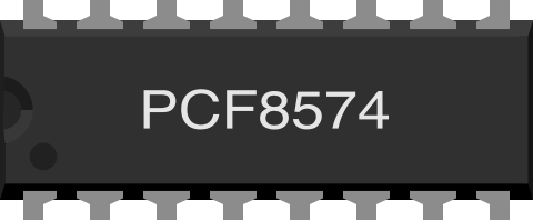
The PCF8574 is an I2C I/O expander manufactured by NXP Semiconductors. It is designed to expand the number of input/output (I/O) pins available to a microcontroller. The device features 8 General Purpose Input/Output (GPIO) pins that can be configured as either inputs or outputs. This makes it ideal for applications where the microcontroller has limited I/O pins but needs to interface with multiple devices.
Explore Projects Built with PCF8574
 Open Project in Cirkit Designer
 Open Project in Cirkit Designer
 Open Project in Cirkit Designer
 Open Project in Cirkit Designer
Explore Projects Built with PCF8574
Open Project in Cirkit DesignerOpen Project in Cirkit DesignerOpen Project in Cirkit DesignerOpen Project in Cirkit DesignerCommon Applications and Use Cases
- Expanding GPIO pins for microcontrollers like Arduino, Raspberry Pi, or ESP32.
- Driving LEDs, relays, or other output devices.
- Reading input from switches, sensors, or keypads.
- Interfacing with LCD displays or other peripherals.
- Applications requiring minimal pin usage for communication (via I2C).
Technical Specifications
Key Technical Details
| Parameter | Value |
|---|---|
| Manufacturer | NXP Semiconductors |
| Part Number | PCF8574AP |
| Communication Protocol | I2C (Inter-Integrated Circuit) |
| Operating Voltage Range | 2.5V to 6V |
| Maximum Sink Current | 25 mA per pin |
| Maximum Source Current | -300 µA per pin |
| I2C Address Range | 0x20 to 0x27 (configurable via A0, A1, A2) |
| GPIO Pins | 8 (P0 to P7) |
| Operating Temperature | -40°C to +85°C |
| Package Type | DIP-16, SO-16, or TSSOP-16 |
Pin Configuration and Descriptions
The PCF8574 comes in a 16-pin package. Below is the pinout and description:
| Pin No. | Pin Name | Description |
|---|---|---|
| 1 | A0 | I2C address selection bit 0 |
| 2 | A1 | I2C address selection bit 1 |
| 3 | A2 | I2C address selection bit 2 |
| 4 | P0 | GPIO pin 0 (input/output) |
| 5 | P1 | GPIO pin 1 (input/output) |
| 6 | P2 | GPIO pin 2 (input/output) |
| 7 | P3 | GPIO pin 3 (input/output) |
| 8 | VSS | Ground (0V) |
| 9 | P4 | GPIO pin 4 (input/output) |
| 10 | P5 | GPIO pin 5 (input/output) |
| 11 | P6 | GPIO pin 6 (input/output) |
| 12 | P7 | GPIO pin 7 (input/output) |
| 13 | INT | Interrupt output (active LOW) |
| 14 | SCL | I2C clock line |
| 15 | SDA | I2C data line |
| 16 | VDD | Power supply (2.5V to 6V) |
Usage Instructions
How to Use the PCF8574 in a Circuit
- Power Supply: Connect the VDD pin to a power source (2.5V to 6V) and the VSS pin to ground.
- I2C Address Configuration: Use the A0, A1, and A2 pins to set the I2C address. These pins can be connected to either VDD (logic HIGH) or VSS (logic LOW) to configure the address.
- Example: If A0, A1, and A2 are all connected to VSS, the I2C address is
0x20.
- Example: If A0, A1, and A2 are all connected to VSS, the I2C address is
- I2C Communication: Connect the SCL and SDA pins to the corresponding I2C pins on the microcontroller.
- GPIO Pins: Use the P0 to P7 pins as inputs or outputs, depending on your application. Pull-up resistors may be required for input configurations.
- Interrupt Pin (Optional): The INT pin can be used to detect changes on input pins. It is active LOW and requires external pull-up.
Important Considerations and Best Practices
- Pull-Up Resistors: The I2C bus requires pull-up resistors on the SCL and SDA lines. Typical values range from 4.7 kΩ to 10 kΩ.
- Current Limitations: Ensure that the sink and source currents of the GPIO pins do not exceed the specified limits.
- Address Conflicts: Avoid I2C address conflicts when using multiple devices on the same bus.
- Interrupt Handling: If using the INT pin, ensure your microcontroller is configured to handle external interrupts.
Example: Using PCF8574 with Arduino UNO
Below is an example of how to use the PCF8574 to control LEDs with an Arduino UNO:
#include <Wire.h> // Include the Wire library for I2C communication

#define PCF8574_ADDRESS 0x20 // I2C address of the PCF8574 (A0, A1, A2 = LOW)

void setup() {
  Wire.begin(); // Initialize I2C communication
  Serial.begin(9600); // Initialize serial communication for debugging

  // Set all GPIO pins to HIGH (turn off LEDs if connected to active LOW)
  Wire.beginTransmission(PCF8574_ADDRESS);
  Wire.write(0xFF); // All pins HIGH
  Wire.endTransmission();
}

void loop() {
  // Example: Toggle GPIO pin P0 every second
  Wire.beginTransmission(PCF8574_ADDRESS);
  Wire.write(0xFE); // Set P0 LOW, others HIGH
  Wire.endTransmission();
  delay(1000); // Wait for 1 second

  Wire.beginTransmission(PCF8574_ADDRESS);
  Wire.write(0xFF); // Set all pins HIGH
  Wire.endTransmission();
  delay(1000); // Wait for 1 second
}
Troubleshooting and FAQs
Common Issues and Solutions
I2C Communication Not Working
- Cause: Incorrect I2C address or wiring.
- Solution: Verify the I2C address configuration (A0, A1, A2) and check the connections for SCL and SDA.
GPIO Pins Not Responding
- Cause: Incorrect pin configuration or insufficient current.
- Solution: Ensure the pins are configured correctly as inputs or outputs. Check the current requirements of connected devices.
Interrupt Pin Not Triggering
- Cause: No pull-up resistor on the INT pin.
- Solution: Add an external pull-up resistor to the INT pin.
Multiple Devices on I2C Bus Not Working
- Cause: Address conflict or insufficient pull-up resistance.
- Solution: Ensure each device has a unique I2C address. Use appropriate pull-up resistor values.
FAQs
Q1: Can the PCF8574 handle analog signals?
A1: No, the PCF8574 is designed for digital I/O only. It cannot process analog signals.
Q2: How many PCF8574 devices can be connected to the same I2C bus?
A2: Up to 8 devices can be connected, as the I2C address range is from 0x20 to 0x27.
Q3: What happens if the power supply exceeds 6V?
A3: Exceeding 6V can damage the device. Always ensure the supply voltage is within the specified range.
Q4: Can the PCF8574 be used with 3.3V microcontrollers?
A4: Yes, the PCF8574 is compatible with 3.3V systems as long as the supply voltage is within the operating range.
This concludes the documentation for the PCF8574 I2C I/O expander.