How to Use switch_off: Examples, Pinouts, and Specs

Introduction
A switch is a fundamental electronic component used to control the flow of current in a circuit. The "off" state of a switch interrupts the current, effectively breaking the circuit and stopping the flow of electricity. Switches are widely used in various applications, including household appliances, industrial machinery, and electronic devices, to provide manual or automated control over electrical circuits.
Explore Projects Built with switch_off
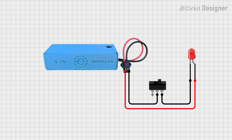

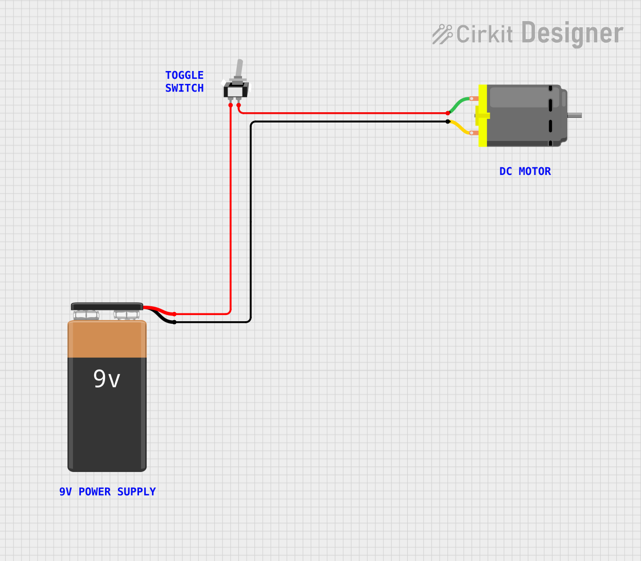
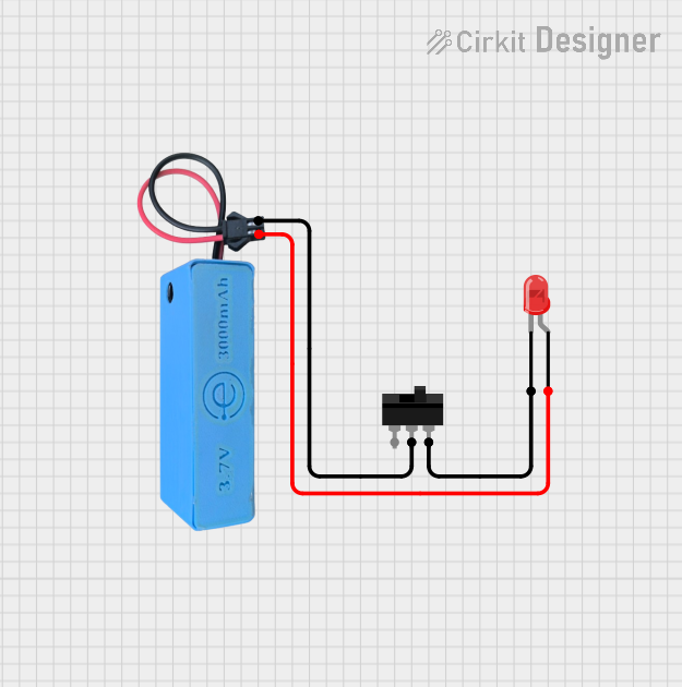
Explore Projects Built with switch_off
Common Applications and Use Cases
- Power control in electronic devices (e.g., turning devices on/off)
- Circuit isolation for safety and maintenance
- User input in control panels and interfaces
- Automation systems and robotics
Technical Specifications
Below are the general technical specifications for a standard switch in its "off" state:
| Parameter | Value |
|---|---|
| Voltage Rating | Typically 3V to 250V (varies by model) |
| Current Rating | Typically 0.1A to 15A (varies by model) |
| Contact Resistance | ≤ 50 mΩ |
| Insulation Resistance | ≥ 100 MΩ |
| Operating Temperature | -40°C to +85°C |
| Mechanical Lifespan | 10,000 to 1,000,000 cycles |
Pin Configuration and Descriptions
Switches generally have two or more terminals. Below is a table describing the pin configuration for a basic Single Pole Single Throw (SPST) switch:
| Pin Name | Description |
|---|---|
| Pin 1 | Input terminal for the electrical current |
| Pin 2 | Output terminal for the electrical current |
For more complex switches (e.g., DPDT, SPDT), additional pins may be present for multiple circuits or configurations.
Usage Instructions
How to Use the Component in a Circuit
- Identify the Terminals: For a basic SPST switch, locate the two terminals (Pin 1 and Pin 2).
- Connect the Circuit:
- Connect Pin 1 to the power source or input signal.
- Connect Pin 2 to the load or output device.
- Operation:
- When the switch is in the "off" position, the circuit is open, and no current flows.
- When the switch is toggled to the "on" position, the circuit is closed, allowing current to flow.
Important Considerations and Best Practices
- Voltage and Current Ratings: Ensure the switch's voltage and current ratings match or exceed the requirements of your circuit to prevent damage or failure.
- Debouncing: Mechanical switches may produce noise or "bouncing" when toggled. Use a capacitor or software debouncing techniques in sensitive circuits.
- Safety: Always disconnect power before wiring or modifying the switch in a circuit.
- Mounting: Secure the switch properly to avoid accidental toggling or damage.
Example: Connecting a Switch to an Arduino UNO
Below is an example of how to use a switch with an Arduino UNO to control an LED:
Circuit Setup
- Connect one terminal of the switch to Arduino's digital pin 2.
- Connect the other terminal of the switch to GND.
- Use a pull-up resistor (10kΩ) between digital pin 2 and 5V to ensure a stable input signal.
- Connect an LED to digital pin 13 with a 220Ω resistor in series.
Code Example
// Define pin numbers
const int switchPin = 2;  // Pin connected to the switch
const int ledPin = 13;    // Pin connected to the LED

void setup() {
  pinMode(switchPin, INPUT_PULLUP); // Set switch pin as input with pull-up resistor
  pinMode(ledPin, OUTPUT);          // Set LED pin as output
}

void loop() {
  int switchState = digitalRead(switchPin); // Read the state of the switch

  if (switchState == LOW) { // If switch is pressed (LOW due to pull-up)
    digitalWrite(ledPin, HIGH); // Turn on the LED
  } else {
    digitalWrite(ledPin, LOW);  // Turn off the LED
  }
}
Troubleshooting and FAQs
Common Issues Users Might Face
Switch Not Working:
- Cause: Incorrect wiring or loose connections.
- Solution: Double-check the wiring and ensure all connections are secure.
Switch Generates Noise or Unstable Signals:
- Cause: Mechanical bouncing of the switch contacts.
- Solution: Add a capacitor across the switch terminals or implement software debouncing.
Switch Overheats:
- Cause: Exceeding the voltage or current rating of the switch.
- Solution: Use a switch with appropriate ratings for your circuit.
LED Does Not Turn On in Arduino Example:
- Cause: Incorrect pin configuration or faulty components.
- Solution: Verify the pin numbers in the code and check the LED and resistor connections.
Solutions and Tips for Troubleshooting
- Use a multimeter to test the continuity of the switch in both "on" and "off" positions.
- Ensure the power supply is functioning correctly and delivering the required voltage.
- Replace the switch if it shows signs of wear or damage after prolonged use.
By following this documentation, you can effectively integrate and troubleshoot a switch in your electronic projects.