
How to Use linino dogRJ45: Examples, Pinouts, and Specs
 Design with linino dogRJ45 in Cirkit Designer
Introduction
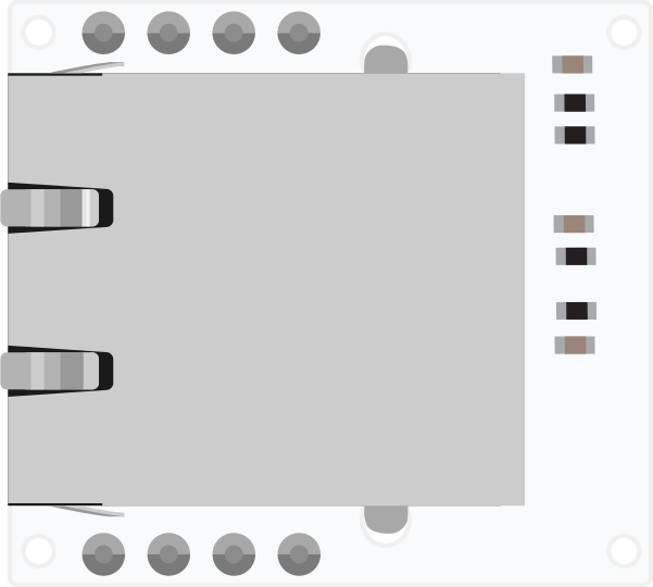
The Linino Dog RJ45 is a network interface module manufactured by Dog Hunter Inc. (Part ID: dogRJ45). This module provides Ethernet connectivity for electronic devices, enabling them to connect to local area networks (LAN) and the internet. It is designed for seamless integration into embedded systems, IoT devices, and microcontroller-based projects.
Explore Projects Built with linino dogRJ45
 Open Project in Cirkit Designer
 Open Project in Cirkit Designer
 Open Project in Cirkit Designer
 Open Project in Cirkit Designer
Explore Projects Built with linino dogRJ45
Open Project in Cirkit DesignerOpen Project in Cirkit DesignerOpen Project in Cirkit DesignerOpen Project in Cirkit DesignerCommon Applications and Use Cases
- Internet of Things (IoT) devices requiring Ethernet connectivity
- Microcontroller-based projects (e.g., Arduino, Raspberry Pi)
- Industrial automation systems
- Smart home devices
- Network-enabled sensors and actuators
Technical Specifications
The Linino Dog RJ45 module is designed to meet the requirements of modern Ethernet communication. Below are its key technical details:
Key Technical Details
| Parameter | Specification |
|---|---|
| Manufacturer | Dog Hunter Inc. |
| Part ID | dogRJ45 |
| Ethernet Standard | IEEE 802.3 (10/100 Mbps) |
| Operating Voltage | 3.3V |
| Power Consumption | 150 mW (typical) |
| Connector Type | RJ45 (8P8C) |
| Communication Protocol | SPI |
| Operating Temperature | -40°C to +85°C |
| Dimensions | 25mm x 20mm x 15mm |
Pin Configuration and Descriptions
The Linino Dog RJ45 module features a 10-pin header for interfacing with microcontrollers or other devices. Below is the pin configuration:
| Pin Number | Pin Name | Description |
|---|---|---|
| 1 | VCC | Power supply input (3.3V) |
| 2 | GND | Ground connection |
| 3 | MISO | Master In Slave Out (SPI data output from the module) |
| 4 | MOSI | Master Out Slave In (SPI data input to the module) |
| 5 | SCK | Serial Clock (SPI clock signal) |
| 6 | CS | Chip Select (active low, used to enable SPI communication) |
| 7 | INT | Interrupt output (used to signal events such as received data) |
| 8 | RESET | Active low reset pin to restart the module |
| 9 | TX+ | Positive differential signal for Ethernet transmission |
| 10 | TX- | Negative differential signal for Ethernet transmission |
Usage Instructions
The Linino Dog RJ45 module is straightforward to use in Ethernet-enabled projects. Below are the steps and best practices for integrating it into your circuit.
How to Use the Component in a Circuit
- Power Supply: Connect the
VCCpin to a 3.3V power source and theGNDpin to ground. - SPI Communication: Connect the
MISO,MOSI,SCK, andCSpins to the corresponding SPI pins on your microcontroller. - Interrupt Handling: Use the
INTpin to detect events such as incoming data packets. - Reset: Connect the
RESETpin to a GPIO pin on your microcontroller for manual or software-controlled resets. - Ethernet Connection: Plug an Ethernet cable into the RJ45 connector to establish a physical network connection.
Important Considerations and Best Practices
- Ensure the module is powered with a stable 3.3V supply to avoid damage.
- Use proper SPI clock settings (typically up to 10 MHz) for reliable communication.
- Keep the Ethernet cable length within the recommended range (up to 100 meters for Cat5e or Cat6 cables).
- Use decoupling capacitors near the power pins to reduce noise and improve stability.
- If using with an Arduino UNO, note that the Arduino operates at 5V logic levels. Use a level shifter or voltage divider to interface with the 3.3V SPI pins of the module.
Example Code for Arduino UNO
Below is an example of how to use the Linino Dog RJ45 module with an Arduino UNO to establish a basic Ethernet connection:
#include <SPI.h>
#include <Ethernet.h>

// Define the MAC address and IP address for the Ethernet module
byte mac[] = { 0xDE, 0xAD, 0xBE, 0xEF, 0xFE, 0xED }; // Replace with your MAC address
IPAddress ip(192, 168, 1, 100); // Replace with your desired IP address

// Initialize the Ethernet server on port 80
EthernetServer server(80);

void setup() {
  // Start the SPI and Ethernet connection
  Ethernet.begin(mac, ip);
  server.begin();

  // Print the IP address to the Serial Monitor
  Serial.begin(9600);
  Serial.print("Server is at ");
  Serial.println(Ethernet.localIP());
}

void loop() {
  // Listen for incoming clients
  EthernetClient client = server.available();
  if (client) {
    Serial.println("New client connected");
    while (client.connected()) {
      if (client.available()) {
        char c = client.read();
        Serial.write(c); // Echo received data to Serial Monitor
        server.write(c); // Echo received data back to the client
      }
    }
    client.stop();
    Serial.println("Client disconnected");
  }
}
Notes on the Code
- Replace the MAC address and IP address with values suitable for your network.
- Ensure the Ethernet library is installed in your Arduino IDE.
- The code sets up a simple web server that echoes received data.
Troubleshooting and FAQs
Common Issues and Solutions
No Ethernet Connectivity
- Ensure the Ethernet cable is securely connected to the RJ45 port.
- Verify that the IP address and MAC address are correctly configured in the code.
- Check the power supply voltage (3.3V) and ensure it is stable.
SPI Communication Fails
- Double-check the SPI connections (MISO, MOSI, SCK, CS) between the module and the microcontroller.
- Ensure the SPI clock speed is within the module's supported range (up to 10 MHz).
Module Not Responding
- Use the
RESETpin to restart the module and clear any errors. - Verify that the
INTpin is properly connected and monitored for events.
- Use the
Slow Network Performance
- Use high-quality Ethernet cables (e.g., Cat5e or Cat6) to reduce signal loss.
- Minimize the length of SPI wires to reduce noise and improve signal integrity.
FAQs
Q: Can the Linino Dog RJ45 module be used with 5V microcontrollers?
A: Yes, but you must use level shifters or voltage dividers to safely interface the 3.3V SPI pins with 5V logic levels.
Q: What is the maximum data rate supported by the module?
A: The module supports up to 100 Mbps Ethernet communication.
Q: Does the module support DHCP?
A: Yes, the module can be configured to use DHCP for automatic IP address assignment.
Q: Can I use this module for PoE (Power over Ethernet)?
A: No, the Linino Dog RJ45 does not support PoE. It requires a separate 3.3V power supply.
By following this documentation, you can effectively integrate the Linino Dog RJ45 module into your projects and troubleshoot common issues.