How to Use Ender 3 Motherboard: Examples, Pinouts, and Specs
Introduction
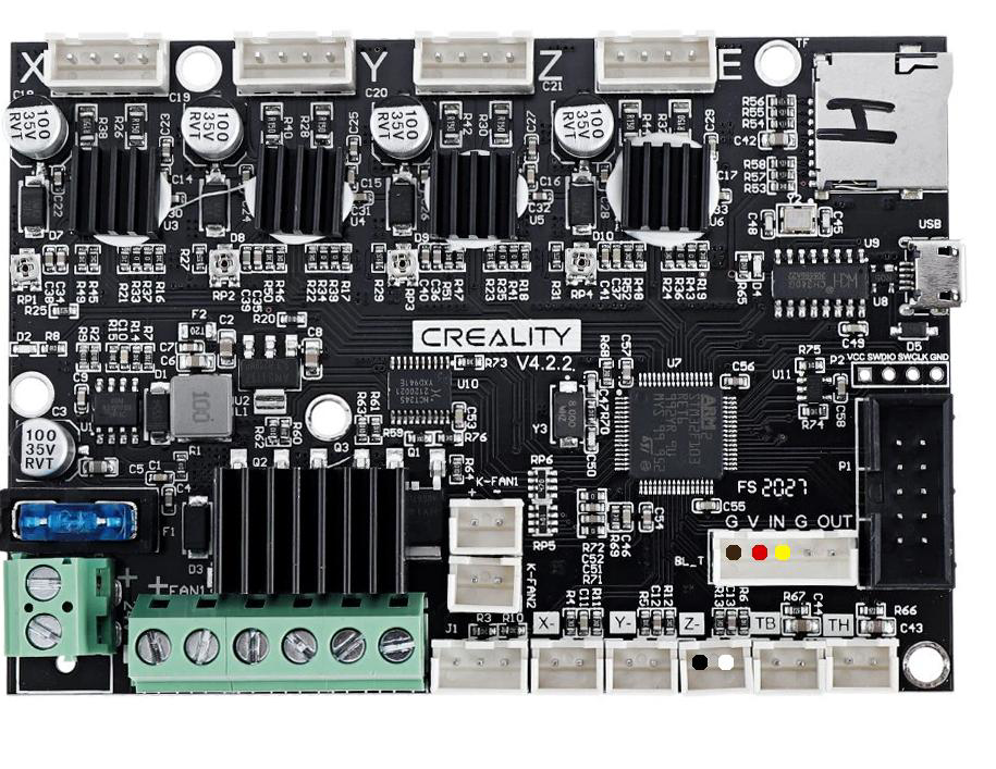
The Ender 3 Motherboard is the central control unit for the Ender 3 3D printer, responsible for managing all critical operations. It controls the stepper motors, regulates the temperature of the hotend and heated bed, and facilitates communication with the printer's user interface. This motherboard is essential for ensuring precise and reliable 3D printing performance.
Explore Projects Built with Ender 3 Motherboard

Explore Projects Built with Ender 3 Motherboard
Common Applications and Use Cases
- Core control unit for the Ender 3 3D printer.
- Upgrading or replacing the stock motherboard for improved performance.
- Customizing firmware to enable advanced features like silent stepper drivers or auto bed leveling.
- Experimenting with open-source firmware such as Marlin for enhanced functionality.
Technical Specifications
The Ender 3 Motherboard comes in different versions, such as the stock Creality V1.1.4, V1.1.5 (silent version), and the upgraded V4.2.2 or V4.2.7. Below are the general specifications:
Key Technical Details
- Microcontroller: Varies by version (e.g., ATmega1284P for V1.x, STM32F103 for V4.x).
- Input Voltage: 12V or 24V DC (depending on the printer's power supply).
- Stepper Driver Support: Integrated A4988 or TMC2208/TMC2209 (silent versions).
- Heated Bed Output: MOSFET-controlled, supports up to 15A.
- Hotend Output: MOSFET-controlled, supports up to 10A.
- Fan Outputs: 2 controllable fan outputs.
- Connectivity: USB Type-B for PC connection, microSD card slot for file transfer.
- Firmware: Compatible with Marlin firmware (open-source).
Pin Configuration and Descriptions
Below is the pin configuration for the Ender 3 Motherboard (V4.2.2 as an example):
| Pin Name | Description |
|---|---|
| X_STEP, X_DIR | Step and direction control for the X-axis stepper motor. |
| Y_STEP, Y_DIR | Step and direction control for the Y-axis stepper motor. |
| Z_STEP, Z_DIR | Step and direction control for the Z-axis stepper motor. |
| E_STEP, E_DIR | Step and direction control for the extruder stepper motor. |
| HEAT_BED | MOSFET output for the heated bed. |
| HEAT_HOTEND | MOSFET output for the hotend heater cartridge. |
| FAN0, FAN1 | Outputs for cooling fans (FAN0 is typically for the part cooling fan). |
| THERM_BED | Input for the heated bed thermistor. |
| THERM_HOTEND | Input for the hotend thermistor. |
| ENDSTOP_X, Y, Z | Inputs for the X, Y, and Z-axis endstop switches. |
| PROBE | Input for an optional auto bed leveling probe (e.g., BLTouch). |
| USB | USB interface for connecting to a PC or sending G-code commands. |
| SD_CARD | MicroSD card slot for loading print files. |
Usage Instructions
How to Use the Ender 3 Motherboard in a Circuit
- Installation: Mount the motherboard securely in the designated slot on the Ender 3 printer.
- Connections:
- Connect the stepper motors to their respective ports (X, Y, Z, and E).
- Attach the thermistors to the THERM_BED and THERM_HOTEND ports.
- Connect the heated bed and hotend heater cartridge to the HEAT_BED and HEAT_HOTEND outputs.
- Plug in the cooling fans to FAN0 and FAN1.
- Attach the endstop switches to the ENDSTOP_X, ENDSTOP_Y, and ENDSTOP_Z inputs.
- If using an auto bed leveling probe, connect it to the PROBE port.
- Power Supply: Ensure the power supply matches the motherboard's voltage requirements (12V or 24V).
- Firmware: Flash the appropriate firmware (e.g., Marlin) using a USB connection and software like Arduino IDE or Visual Studio Code with PlatformIO.
Important Considerations and Best Practices
- Firmware Compatibility: Ensure the firmware version matches the motherboard version (e.g., V1.x or V4.x).
- Cooling: Provide adequate cooling for the motherboard, especially if using high-current components.
- Wiring: Double-check all connections to avoid short circuits or damage to components.
- Stepper Drivers: If upgrading to silent stepper drivers (e.g., TMC2208), configure the firmware accordingly.
- Auto Bed Leveling: If installing a BLTouch or similar probe, update the firmware to enable this feature.
Example Code for Arduino-Compatible Firmware (Marlin)
Below is an example of configuring the Ender 3 Motherboard for a BLTouch probe in Marlin firmware:
// Uncomment the following line to enable BLTouch support
#define BLTOUCH

// Set the probe offset from the nozzle (adjust values as needed)
#define NOZZLE_TO_PROBE_OFFSET { -44, -9, 0 }

// Enable auto bed leveling
#define AUTO_BED_LEVELING_BILINEAR

// Define the size of the bed leveling grid
#define GRID_MAX_POINTS_X 3
#define GRID_MAX_POINTS_Y 3

// Enable Z-safe homing to ensure the probe is positioned correctly
#define Z_SAFE_HOMING

// Set the homing feedrate for the Z-axis
#define HOMING_FEEDRATE_Z (4*60)
Upload the modified firmware to the motherboard using a USB connection and a flashing tool like PlatformIO.
Troubleshooting and FAQs
Common Issues and Solutions
Problem: The printer does not power on.
- Solution: Check the power supply connections and ensure the voltage matches the motherboard's requirements.
Problem: Stepper motors are not moving.
- Solution: Verify the stepper motor connections and ensure the firmware is configured correctly.
Problem: The hotend or heated bed is not heating.
- Solution: Check the MOSFET outputs and thermistor connections. Ensure the firmware temperature limits are set correctly.
Problem: BLTouch probe is not working.
- Solution: Confirm the probe is connected to the correct port and the firmware is configured for BLTouch.
Problem: USB connection is not recognized by the PC.
- Solution: Install the appropriate USB drivers for the motherboard (e.g., CH340 for V1.x or STM32 drivers for V4.x).
Tips for Troubleshooting
- Use a multimeter to check voltage levels and continuity.
- Refer to the motherboard's schematic for detailed pinout information.
- Consult the Marlin firmware documentation for advanced configuration options.
By following this documentation, users can effectively install, configure, and troubleshoot the Ender 3 Motherboard for optimal 3D printing performance.