How to Use BN0 O55 (9DoF IMU): Examples, Pinouts, and Specs
Introduction
The BN0 O55 is a 9 Degrees of Freedom (9DoF) Inertial Measurement Unit (IMU) developed by Adafruit. It integrates an accelerometer, gyroscope, and magnetometer into a single compact module, enabling precise motion tracking and orientation sensing. This component is ideal for applications requiring accurate motion data, such as robotics, navigation systems, drones, and wearable devices.
Explore Projects Built with BN0 O55 (9DoF IMU)


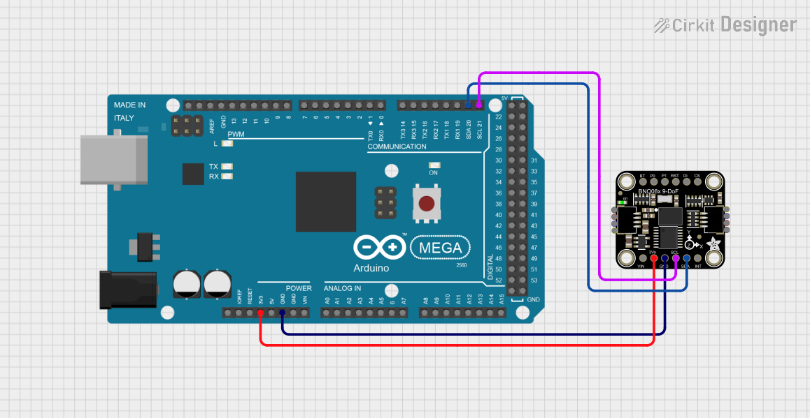
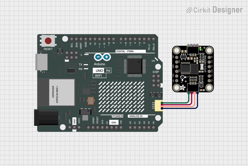
Explore Projects Built with BN0 O55 (9DoF IMU)
Common Applications
- Robotics for motion and orientation tracking
- Navigation systems for determining heading and position
- Drones and UAVs for stabilization and control
- Wearable devices for activity monitoring
- Gaming and virtual reality for motion sensing
Technical Specifications
The BN0 O55 is a high-performance IMU with the following key specifications:
| Parameter | Value |
|---|---|
| Operating Voltage | 3.3V to 5V |
| Communication Protocol | I2C and UART |
| Accelerometer Range | ±2g, ±4g, ±8g, ±16g |
| Gyroscope Range | ±125°/s, ±250°/s, ±500°/s, ±1000°/s, ±2000°/s |
| Magnetometer Range | ±1300µT |
| Operating Temperature | -40°C to +85°C |
| Dimensions | 20mm x 20mm x 3mm |
| Power Consumption | ~3mA (typical) |
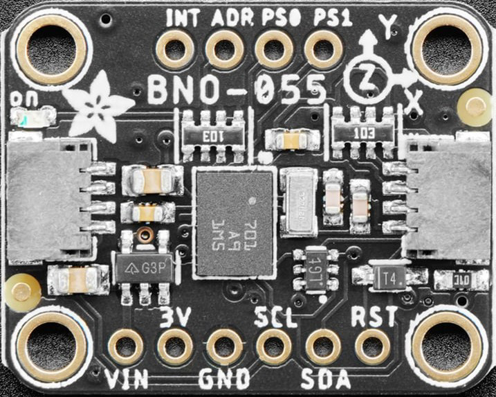
Pin Configuration and Descriptions
The BN0 O55 features a standard pinout for easy integration into circuits. Below is the pin configuration:
| Pin | Name | Description |
|---|---|---|
| 1 | VIN | Power input (3.3V to 5V) |
| 2 | GND | Ground connection |
| 3 | SDA | I2C data line |
| 4 | SCL | I2C clock line |
| 5 | TX | UART transmit line |
| 6 | RX | UART receive line |
| 7 | INT | Interrupt pin for event notifications |
| 8 | RST | Reset pin to restart the module |
Usage Instructions
How to Use the BN0 O55 in a Circuit
- Power the Module: Connect the VIN pin to a 3.3V or 5V power source and the GND pin to ground.
- Choose Communication Protocol:
- For I2C, connect the SDA and SCL pins to the corresponding pins on your microcontroller.
- For UART, connect the TX and RX pins to the UART pins on your microcontroller.
- Interrupt and Reset: Optionally, connect the INT pin to monitor events and the RST pin for resetting the module.
- Install Required Libraries: If using an Arduino, install the Adafruit BNO055 library from the Arduino Library Manager.
Important Considerations
- Voltage Levels: Ensure the module operates within the specified voltage range (3.3V to 5V).
- Orientation: Mount the module securely to avoid vibrations or misalignment that could affect sensor readings.
- Calibration: Perform sensor calibration (accelerometer, gyroscope, and magnetometer) for accurate data.
- I2C Address: The default I2C address is
0x28. Ensure no address conflicts if multiple I2C devices are used.
Example Code for Arduino UNO
Below is an example of how to use the BN0 O55 with an Arduino UNO via I2C:
#include <Wire.h>
#include <Adafruit_Sensor.h>
#include <Adafruit_BNO055.h>

// Create an instance of the BNO055 sensor
Adafruit_BNO055 bno = Adafruit_BNO055(55);

void setup() {
  Serial.begin(9600); // Initialize serial communication
  while (!Serial) {
    delay(10); // Wait for the serial port to be ready
  }

  // Initialize the BNO055 sensor
  if (!bno.begin()) {
    Serial.println("Error: BNO055 not detected. Check connections.");
    while (1);
  }

  Serial.println("BNO055 initialized successfully!");

  // Perform sensor calibration
  bno.setExtCrystalUse(true); // Use external crystal for better accuracy
}

void loop() {
  // Get orientation data (Euler angles)
  sensors_event_t event;
  bno.getEvent(&event);

  // Print orientation data to the serial monitor
  Serial.print("Heading: ");
  Serial.print(event.orientation.x);
  Serial.print("°\tPitch: ");
  Serial.print(event.orientation.y);
  Serial.print("°\tRoll: ");
  Serial.print(event.orientation.z);
  Serial.println("°");

  delay(500); // Delay for readability
}
Notes:
- Install the "Adafruit BNO055" library via the Arduino Library Manager before running the code.
- Ensure proper wiring between the Arduino UNO and the BN0 O55 module.
Troubleshooting and FAQs
Common Issues
Sensor Not Detected:
- Cause: Incorrect wiring or I2C address conflict.
- Solution: Verify connections and ensure the correct I2C address (
0x28) is used.
Inaccurate Readings:
- Cause: Module not calibrated or mounted improperly.
- Solution: Perform sensor calibration and ensure the module is securely mounted.
No Data Output:
- Cause: Incorrect baud rate or communication protocol.
- Solution: Ensure the baud rate matches the code and the correct protocol (I2C or UART) is used.
FAQs
Q: Can the BN0 O55 operate at 5V logic levels?
A: Yes, the module is compatible with both 3.3V and 5V logic levels.Q: How do I reset the module?
A: Pull the RST pin low momentarily to reset the module.Q: Is the BN0 O55 suitable for outdoor use?
A: Yes, but ensure it is protected from moisture and extreme environmental conditions.Q: Can I use multiple BN0 O55 modules on the same I2C bus?
A: Yes, but you must configure each module with a unique I2C address.
This documentation provides a comprehensive guide to using the BN0 O55 IMU for motion tracking and orientation sensing. For further assistance, refer to the Adafruit support resources.