How to Use LM386-based sensor: Examples, Pinouts, and Specs
Introduction
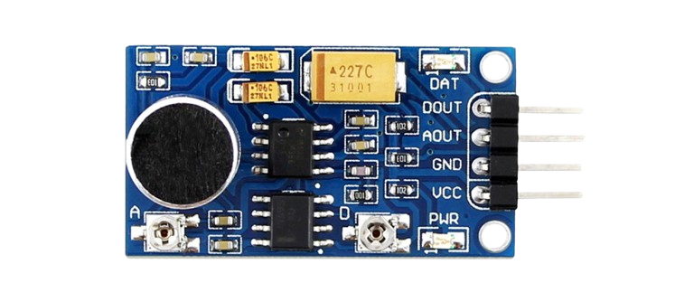
The LM386-based sensor is a versatile circuit that leverages the LM386 operational amplifier to amplify small input signals. This makes it ideal for applications requiring the detection of low-level signals, such as audio sensing, environmental monitoring, and vibration detection. The LM386 is a low-voltage audio power amplifier, but in this sensor configuration, it is adapted to amplify weak signals for further processing or measurement.
Explore Projects Built with LM386-based sensor

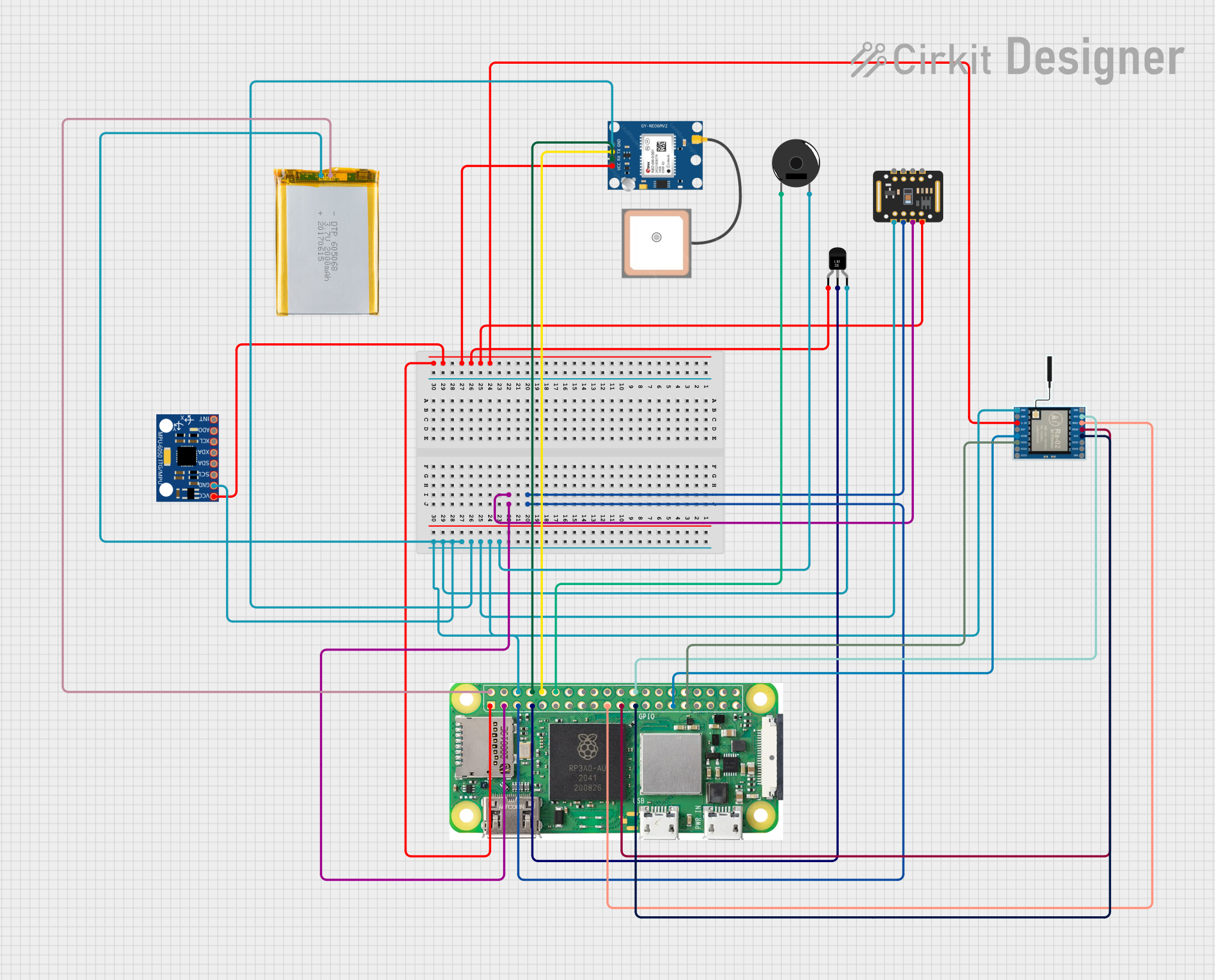
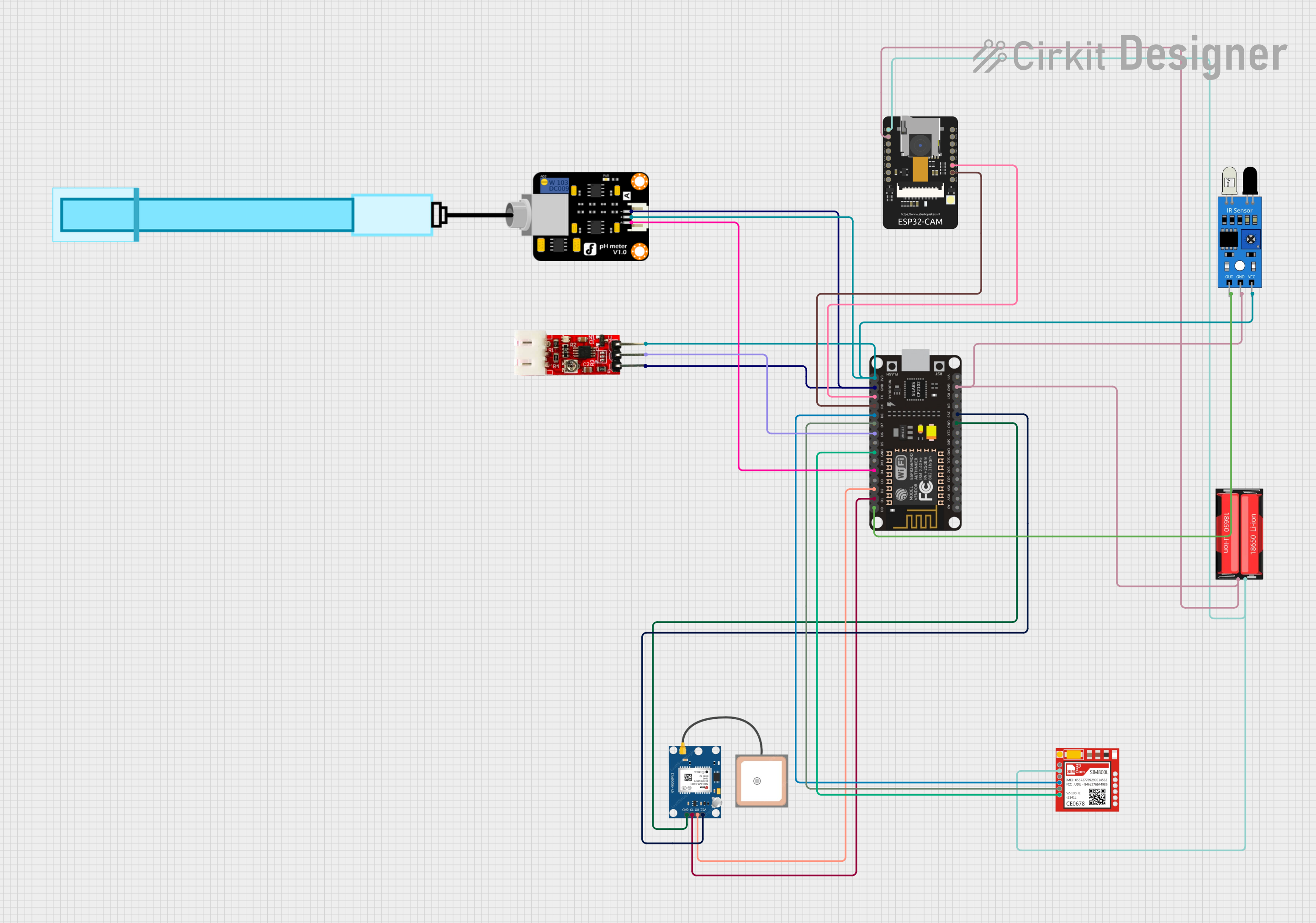
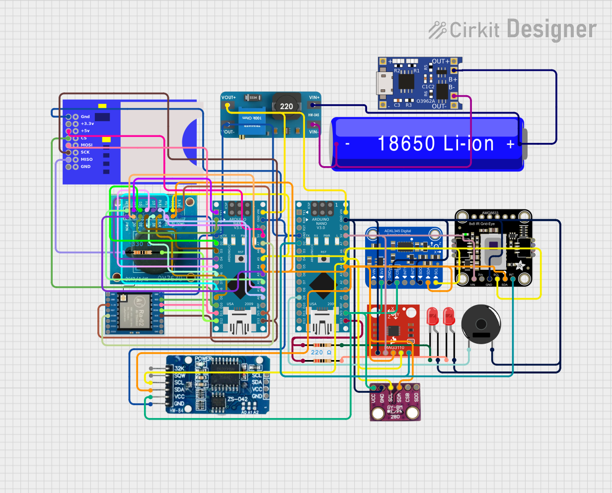
Explore Projects Built with LM386-based sensor
Common Applications
- Audio signal detection and amplification
- Environmental sensing (e.g., sound level monitoring)
- Vibration or motion detection
- Signal conditioning for microcontroller-based systems
Technical Specifications
Key Technical Details
- Operating Voltage: 4V to 12V (typical: 9V)
- Quiescent Current: 4mA (typical)
- Voltage Gain: Adjustable from 20 to 200 (default: 20)
- Input Impedance: High (determined by external components)
- Output Impedance: Low (suitable for driving loads)
- Frequency Response: 300 Hz to 300 kHz (depending on configuration)
- Output Power: 250mW at 8Ω load (with 9V supply)
Pin Configuration and Descriptions
The LM386 IC is an 8-pin DIP (Dual Inline Package). Below is the pinout and description for the LM386 in the context of the sensor circuit:
| Pin Number | Pin Name | Description |
|---|---|---|
| 1 | Gain | Connect to Pin 8 via a capacitor to increase gain (default gain is 20). |
| 2 | Inverting Input | Negative input for the amplifier. Connect to ground or input signal. |
| 3 | Non-Inverting Input | Positive input for the amplifier. Connect to the input signal source. |
| 4 | Ground (GND) | Connect to the circuit ground. |
| 5 | Output | Amplified signal output. |
| 6 | Vcc | Power supply input (4V to 12V). |
| 7 | Bypass | Optional pin for noise filtering. Connect a capacitor to ground if needed. |
| 8 | Gain | Connect to Pin 1 via a capacitor to increase gain. |
Usage Instructions
How to Use the LM386-Based Sensor in a Circuit
- Power Supply: Connect the LM386 to a stable DC power supply (4V to 12V). A 9V battery is commonly used for portable applications.
- Input Signal: Connect the signal source (e.g., microphone, sensor, or transducer) to the non-inverting input (Pin 3). Use a coupling capacitor to block DC components if necessary.
- Gain Adjustment: To increase the gain, connect a capacitor (typically 10µF) between Pins 1 and 8. For the default gain of 20, leave these pins unconnected.
- Output Signal: The amplified signal is available at Pin 5. Connect this pin to the next stage of your circuit (e.g., microcontroller ADC or speaker).
- Bypass Capacitor: For improved stability and noise reduction, connect a capacitor (10µF) between Pin 7 and ground.
- Decoupling Capacitor: Place a decoupling capacitor (e.g., 100µF) between the power supply (Pin 6) and ground to minimize power supply noise.
Important Considerations and Best Practices
- Input Signal Level: Ensure the input signal does not exceed the maximum input voltage range of the LM386.
- Heat Dissipation: The LM386 is a low-power device, but ensure proper ventilation if used at high gain or output power.
- Noise Reduction: Use shielded cables for input signals and place bypass capacitors close to the IC to reduce noise.
- Load Impedance: The output is designed to drive low-impedance loads (e.g., 8Ω speakers). For higher impedance loads, use a buffer stage.
Example: Connecting to an Arduino UNO
The LM386-based sensor can be used to amplify signals for an Arduino UNO's analog input. Below is an example of how to connect and read the amplified signal:
Circuit Connections
- Connect the LM386 output (Pin 5) to an analog input pin (e.g., A0) on the Arduino.
- Use a 10kΩ resistor to pull the analog input pin to ground for stability.
- Power the LM386 circuit with a 9V battery or the Arduino's 5V pin.
Arduino Code
// LM386-Based Sensor Example Code
// This code reads the amplified signal from the LM386 sensor and prints the
// analog value to the Serial Monitor.

const int sensorPin = A0; // Analog pin connected to LM386 output

void setup() {
  Serial.begin(9600); // Initialize serial communication at 9600 baud
}

void loop() {
  int sensorValue = analogRead(sensorPin); // Read the analog value
  Serial.print("Sensor Value: ");
  Serial.println(sensorValue); // Print the value to the Serial Monitor
  delay(100); // Delay for stability
}
Troubleshooting and FAQs
Common Issues and Solutions
No Output Signal:
- Check the power supply connections and ensure the LM386 is receiving the correct voltage.
- Verify that the input signal is properly connected to Pin 3.
- Ensure the gain configuration (Pins 1 and 8) is correct for your application.
Distorted Output:
- Reduce the input signal amplitude to avoid overloading the amplifier.
- Check the load impedance and ensure it matches the LM386's output specifications.
- Add a bypass capacitor (10µF) to Pin 7 to reduce noise.
High Noise Levels:
- Use shielded cables for input signals to minimize interference.
- Place decoupling capacitors (e.g., 100µF) close to the power supply pins.
Overheating:
- Ensure the LM386 is not driving a load with too low an impedance.
- Reduce the gain or output power if overheating persists.
FAQs
Q: Can I use the LM386-based sensor for audio applications?
A: Yes, the LM386 is well-suited for audio signal amplification and can be used with microphones or other audio sources.
Q: What is the maximum gain I can achieve with this sensor?
A: The LM386 can achieve a maximum gain of 200 by connecting a 10µF capacitor between Pins 1 and 8.
Q: Can I power the LM386-based sensor directly from an Arduino?
A: Yes, the LM386 can be powered from the Arduino's 5V pin, but ensure the total current draw of your circuit does not exceed the Arduino's limits.
Q: How do I filter noise in the output signal?
A: Use a bypass capacitor (10µF) on Pin 7 and a decoupling capacitor (100µF) on the power supply to reduce noise.