Cirkit Designer Logo
Cirkit Designer
Your all-in-one circuit design IDE
Home / 
Component Documentation

How to Use SSR-10A: Examples, Pinouts, and Specs

Image of SSR-10A
Cirkit Designer LogoDesign with SSR-10A in Cirkit Designer

Introduction

The SSR-10A is a Solid State Relay (SSR) designed for high-speed, silent switching of AC loads without the mechanical wear and tear associated with traditional electromechanical relays. It is ideal for a wide range of applications including industrial automation, home automation, and temperature control systems.

Explore Projects Built with SSR-10A

Use Cirkit Designer to design, explore, and prototype these projects online. Some projects support real-time simulation. Click "Open Project" to start designing instantly!
Temperature-Controlled Heating System with SSR and Titanium Resistor
Image of Wire Cut Four Slider 33-2 & 33-3 (Old): A project utilizing SSR-10A in a practical application
This circuit is a temperature control system that uses a temperature controller to regulate a heating titanium resistor via a solid-state relay (SSR). The power transformer supplies the necessary voltage to the temperature controller, which in turn controls the SSR to manage the heating element.
Cirkit Designer LogoOpen Project in Cirkit Designer
PID Temperature Control System with Thermocouple and SSR
Image of IR: A project utilizing SSR-10A in a practical application
This circuit is a temperature control system that uses a thermocouple to measure temperature and a PID controller to regulate it. The PID controller drives a solid-state relay (SSR) to control an external load, with power supplied through an AC inlet socket.
Cirkit Designer LogoOpen Project in Cirkit Designer
Battery-Powered Line Following Robot with IR Sensors and Cytron URC10 Motor Controller
Image of URC10 SUMO AUTO: A project utilizing SSR-10A in a practical application
This circuit is a robotic control system that uses multiple IR sensors for line detection and obstacle avoidance, powered by a 3S LiPo battery. The Cytron URC10 motor driver, controlled by a microcontroller, drives two GM25 DC motors based on input from the sensors and a rocker switch, with a 7-segment panel voltmeter displaying the battery voltage.
Cirkit Designer LogoOpen Project in Cirkit Designer
Satellite-Based Timing and Navigation System with SDR and Atomic Clock Synchronization
Image of GPS 시스템 측정 구성도_Confirm: A project utilizing SSR-10A in a practical application
This circuit appears to be a complex system involving power supply management, GPS and timing synchronization, and data communication. It includes a SI-TEX G1 Satellite Compass for GPS data, an XHTF1021 Atomic Rubidium Clock for precise timing, and Ettus USRP B200 units for software-defined radio communication. Power is supplied through various SMPS units and distributed via terminal blocks and DC jacks. Data communication is facilitated by Beelink MINI S12 N95 computers, RS232 splitters, and a 1000BASE-T Media Converter for network connectivity. RF Directional Couplers are used to interface antennas with the USRP units, and the entire system is likely contained within cases for protection and organization.
Cirkit Designer LogoOpen Project in Cirkit Designer

Explore Projects Built with SSR-10A

Use Cirkit Designer to design, explore, and prototype these projects online. Some projects support real-time simulation. Click "Open Project" to start designing instantly!
Image of Wire Cut Four Slider 33-2 & 33-3 (Old): A project utilizing SSR-10A in a practical application
Temperature-Controlled Heating System with SSR and Titanium Resistor
This circuit is a temperature control system that uses a temperature controller to regulate a heating titanium resistor via a solid-state relay (SSR). The power transformer supplies the necessary voltage to the temperature controller, which in turn controls the SSR to manage the heating element.
Cirkit Designer LogoOpen Project in Cirkit Designer
Image of IR: A project utilizing SSR-10A in a practical application
PID Temperature Control System with Thermocouple and SSR
This circuit is a temperature control system that uses a thermocouple to measure temperature and a PID controller to regulate it. The PID controller drives a solid-state relay (SSR) to control an external load, with power supplied through an AC inlet socket.
Cirkit Designer LogoOpen Project in Cirkit Designer
Image of URC10 SUMO AUTO: A project utilizing SSR-10A in a practical application
Battery-Powered Line Following Robot with IR Sensors and Cytron URC10 Motor Controller
This circuit is a robotic control system that uses multiple IR sensors for line detection and obstacle avoidance, powered by a 3S LiPo battery. The Cytron URC10 motor driver, controlled by a microcontroller, drives two GM25 DC motors based on input from the sensors and a rocker switch, with a 7-segment panel voltmeter displaying the battery voltage.
Cirkit Designer LogoOpen Project in Cirkit Designer
Image of GPS 시스템 측정 구성도_Confirm: A project utilizing SSR-10A in a practical application
Satellite-Based Timing and Navigation System with SDR and Atomic Clock Synchronization
This circuit appears to be a complex system involving power supply management, GPS and timing synchronization, and data communication. It includes a SI-TEX G1 Satellite Compass for GPS data, an XHTF1021 Atomic Rubidium Clock for precise timing, and Ettus USRP B200 units for software-defined radio communication. Power is supplied through various SMPS units and distributed via terminal blocks and DC jacks. Data communication is facilitated by Beelink MINI S12 N95 computers, RS232 splitters, and a 1000BASE-T Media Converter for network connectivity. RF Directional Couplers are used to interface antennas with the USRP units, and the entire system is likely contained within cases for protection and organization.
Cirkit Designer LogoOpen Project in Cirkit Designer

Common Applications and Use Cases

  • Controlling high-power devices such as heaters, motors, and lights.
  • PID temperature control in soldering stations, ovens, and incubators.
  • Home automation for controlling appliances remotely.
  • Switching of resistive and inductive loads in industrial automation.

Technical Specifications

Key Technical Details

  • Control Voltage Range: 3-32V DC
  • Load Voltage Range: 24-380V AC
  • Maximum Current Rating: 10A
  • Isolation: Opto-isolation between input and output
  • Zero Cross: Yes, for reduced electrical noise
  • Response Time: Fast on/off time, typically less than 10ms

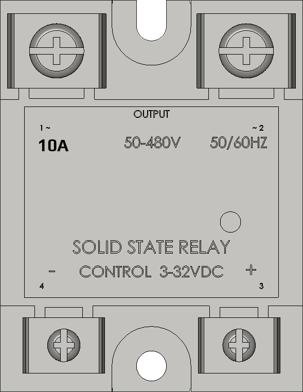
Pin Configuration and Descriptions

Pin Number Description Notes
1 Control Voltage (+) Connect to DC+ (3-32V)
2 Control Voltage (-) Connect to DC-
3 Load Voltage (AC) Connect to one side of the AC load
4 Load Voltage (AC) Connect to the other side of the AC load

Usage Instructions

How to Use the SSR-10A in a Circuit

  1. Control Side Connection:

    • Connect the positive terminal of the DC control signal to pin 1.
    • Connect the negative terminal of the DC control signal to pin 2.
  2. Load Side Connection:

    • Connect one terminal of the AC load to pin 3.
    • Connect the other terminal of the AC load to pin 4.
  3. Powering the SSR:

    • Apply a DC voltage within the specified range (3-32V DC) to the control side to switch the relay on.
    • Remove the control voltage to switch the relay off.

Important Considerations and Best Practices

  • Ensure the load does not exceed the maximum current rating of 10A.
  • Use proper heat sinking if the relay is to be used near its maximum rating.
  • Consider using a snubber circuit for inductive loads to protect against voltage spikes.
  • Always ensure proper isolation between the control and load circuits for safety.

Troubleshooting and FAQs

Common Issues Users Might Face

  • SSR does not switch on: Check if the control voltage is within the specified range and properly connected.
  • SSR overheats: Ensure the current through the SSR does not exceed 10A and that adequate heat sinking is in place.
  • Load does not turn off: Verify that the control voltage is completely removed and that there are no shorts on the load side.

Solutions and Tips for Troubleshooting

  • Double-check wiring connections according to the pin configuration.
  • Measure the control voltage to ensure it falls within the specified range.
  • For inductive loads, consider using a snubber circuit to manage voltage spikes.

FAQs

Q: Can the SSR-10A be used to switch DC loads? A: No, the SSR-10A is designed for AC loads only.

Q: Is there a need for a heatsink? A: For continuous operation near the 10A limit, a heatsink is recommended to dissipate heat.

Q: How do I know if the SSR is on? A: Some SSRs have an LED indicator. If not, measuring the voltage across the load terminals when the control voltage is applied can confirm operation.

Example Code for Arduino UNO

// Example code to control an SSR-10A with an Arduino UNO

const int ssrPin = 7; // Connect the control voltage (+) to Digital Pin 7

void setup() {
  pinMode(ssrPin, OUTPUT); // Set the SSR pin as an output
}

void loop() {
  digitalWrite(ssrPin, HIGH); // Turn on the SSR (apply control voltage)
  delay(5000);                // Keep the SSR on for 5 seconds
  digitalWrite(ssrPin, LOW);  // Turn off the SSR (remove control voltage)
  delay(5000);                // Keep the SSR off for 5 seconds
}

Note: Ensure that the control voltage from the Arduino matches the SSR's requirements. Use a suitable driver if necessary.