How to Use MCB 1 Phase: Examples, Pinouts, and Specs
Introduction
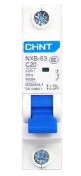
The MCB 1 Phase (Miniature Circuit Breaker) is a compact, electromechanical device designed to protect single-phase electrical circuits from overcurrent conditions, such as overloads and short circuits. It automatically disconnects the circuit when the current exceeds a predefined threshold, ensuring the safety of connected devices and reducing the risk of electrical fires.
Explore Projects Built with MCB 1 Phase


Explore Projects Built with MCB 1 Phase
Common Applications and Use Cases
- Residential and commercial electrical systems
- Protection of lighting circuits, appliances, and power outlets
- Industrial control panels and machinery
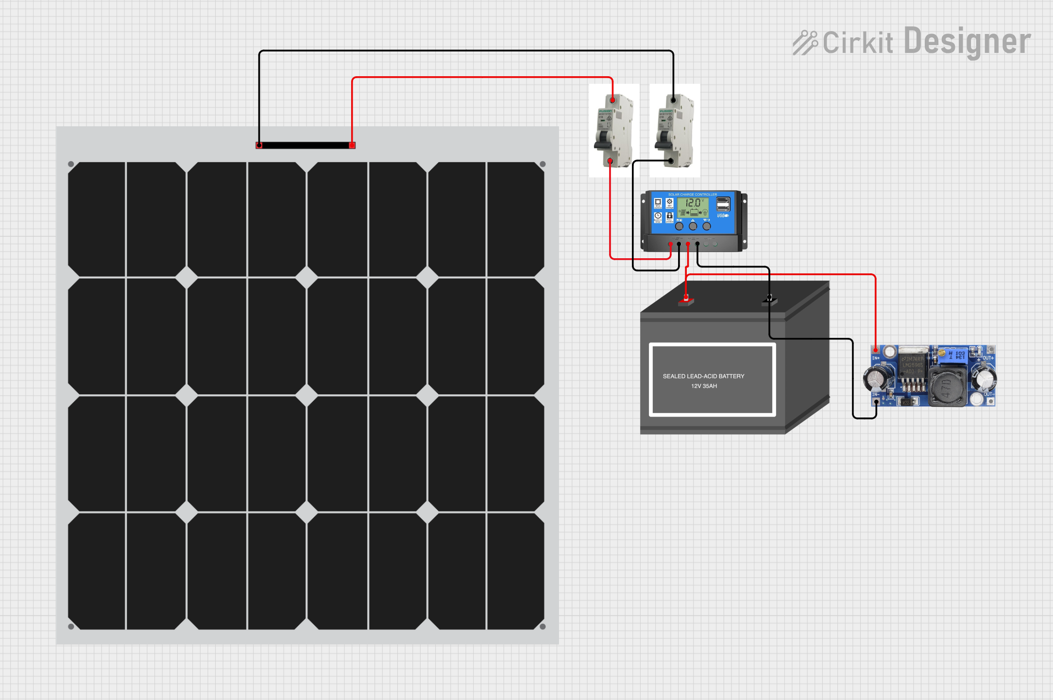
- Renewable energy systems (e.g., solar inverters)
- Backup power systems and generators
Technical Specifications
The following table outlines the key technical details of the MCB 1 Phase:
| Parameter | Value |
|---|---|
| Rated Voltage | 230V AC |
| Rated Current | 6A, 10A, 16A, 20A, 32A, 40A |
| Breaking Capacity | 6kA (6000A) |
| Frequency | 50/60 Hz |
| Tripping Curve | B, C, or D (depending on model) |
| Number of Poles | 1 (Single Phase) |
| Operating Temperature | -5°C to +55°C |
| Mounting Type | DIN Rail (35mm) |
| Standards Compliance | IEC 60898-1, IS/IEC 60947-2 |
Pin Configuration and Descriptions
The MCB 1 Phase has two primary connection terminals:
| Terminal | Description |
|---|---|
| Line (Input) | Connects to the incoming live wire from the power source. |
| Load (Output) | Connects to the outgoing live wire that supplies power to the protected circuit. |
Usage Instructions
How to Use the MCB 1 Phase in a Circuit
Mounting the MCB:
- Install the MCB on a standard 35mm DIN rail in the distribution box or control panel.
- Ensure the MCB is securely locked into place to prevent movement during operation.
Wiring the MCB:
- Connect the incoming live wire (line) to the input terminal of the MCB.
- Connect the outgoing live wire (load) to the output terminal of the MCB.
- Ensure all connections are tight and secure to avoid loose contacts.
Testing the MCB:
- After installation, switch on the MCB and verify that the connected circuit is powered.
- Press the test button (if available) to ensure the MCB trips correctly.
Resetting the MCB:
- In the event of a trip, identify and resolve the cause of the overcurrent (e.g., unplug faulty devices).
- Flip the MCB switch to the "ON" position to restore power.
Important Considerations and Best Practices
- Always select an MCB with a current rating suitable for the connected load.
- Use the appropriate tripping curve (B, C, or D) based on the application:
- B Curve: For residential and light commercial loads.
- C Curve: For inductive loads like motors and transformers.
- D Curve: For high inrush current loads like industrial equipment.
- Ensure proper grounding of the electrical system to enhance safety.
- Periodically inspect the MCB for signs of wear, damage, or overheating.
Arduino UNO Integration
While MCBs are not directly connected to microcontrollers like the Arduino UNO, they can be used in conjunction with relays or solid-state switches to protect circuits controlled by the Arduino. Below is an example of how an MCB might be used in a project:
/*
  Example: Controlling a Load with an MCB and Relay
  This code demonstrates how to control a load using a relay module
  while protecting the circuit with an MCB.

  Note: The MCB is connected in series with the load to provide overcurrent
  protection. The relay is controlled by the Arduino.
*/

const int relayPin = 7; // Pin connected to the relay module

void setup() {
  pinMode(relayPin, OUTPUT); // Set the relay pin as an output
  digitalWrite(relayPin, LOW); // Ensure the relay is off at startup
}

void loop() {
  // Turn the relay on (activates the load)
  digitalWrite(relayPin, HIGH);
  delay(5000); // Keep the load on for 5 seconds

  // Turn the relay off (deactivates the load)
  digitalWrite(relayPin, LOW);
  delay(5000); // Keep the load off for 5 seconds
}
Troubleshooting and FAQs
Common Issues and Solutions
MCB Trips Frequently:
- Cause: Overloaded circuit or short circuit.
- Solution: Reduce the load on the circuit or identify and fix the short circuit.
MCB Does Not Trip During Overcurrent:
- Cause: Faulty MCB or incorrect current rating.
- Solution: Replace the MCB with a properly rated one and test its functionality.
MCB Feels Hot to the Touch:
- Cause: Loose connections or excessive current.
- Solution: Tighten all connections and ensure the load does not exceed the MCB's rating.
MCB Does Not Reset After Tripping:
- Cause: Persistent fault in the circuit.
- Solution: Inspect the circuit for faults and resolve them before resetting the MCB.
FAQs
Q: Can I use an MCB 1 Phase for a three-phase system?
A: No, the MCB 1 Phase is designed specifically for single-phase circuits. For three-phase systems, use a three-phase MCB.Q: How do I choose the correct MCB rating for my circuit?
A: Calculate the total current drawn by the connected devices and select an MCB with a slightly higher rating. For example, if the load is 12A, use a 16A MCB.Q: Can an MCB protect against electric shocks?
A: No, an MCB provides overcurrent protection. For protection against electric shocks, use a Residual Current Device (RCD) or a combination of MCB and RCD.Q: How often should I test my MCB?
A: Test the MCB at least once a year or as recommended by the manufacturer to ensure proper functionality.