
Cirkit Designer
Your all-in-one circuit design IDE
Home /
Component Documentation
How to Use vcc: Examples, Pinouts, and Specs
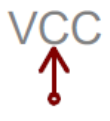
 Design with vcc in Cirkit Designer
Introduction
- Vcc is the voltage supply reference point in a circuit, typically representing the positive supply voltage. It is a critical concept in electronics, as it provides the necessary power for active components like transistors, integrated circuits (ICs), and microcontrollers to operate.
- Common applications include powering digital and analog circuits, serving as a reference voltage for logic levels, and enabling the operation of microcontrollers, sensors, and other electronic components.
Explore Projects Built with vcc
High Voltage Generator with Push Switch Activation
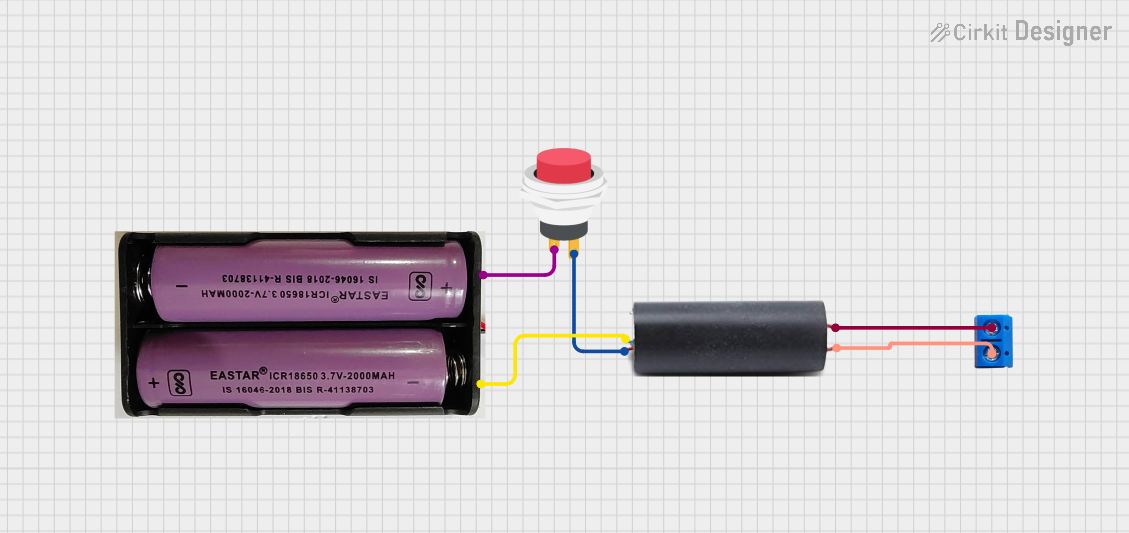
This circuit features a high voltage generator connected to a terminal PCB for output, with its power supply controlled by a 2-pin push switch. The high voltage generator's VCC is connected through the switch, allowing the user to turn the high voltage output on and off. The circuit is powered by a 7.4V battery, with the positive terminal connected to the switch and the negative terminal connected to the generator's ground.
Open Project in Cirkit DesignerSolar Panel to 12V Battery Charging Circuit
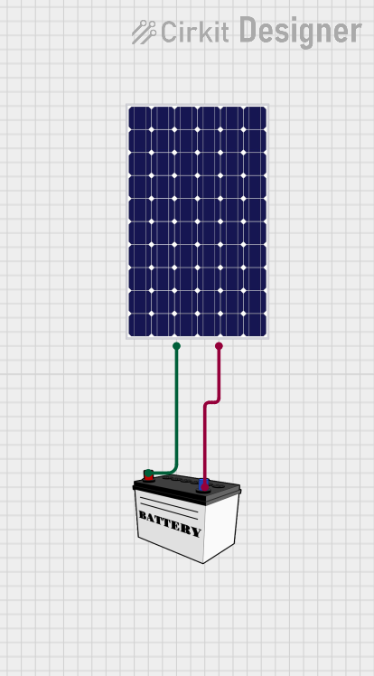
This circuit connects a solar panel to a 12V battery for charging purposes. The positive terminal of the solar panel is connected to the VCC of the battery, and the negative terminal is connected to the GND of the battery, allowing for energy transfer from the solar panel to the battery.
Open Project in Cirkit DesignerCellular-Enabled IoT Device with Real-Time Clock and Power Management

This circuit features a LilyGo-SIM7000G module for cellular communication and GPS functionality, interfaced with an RTC DS3231 for real-time clock capabilities. It includes voltage sensing through two voltage sensor modules, and uses an 8-channel opto-coupler for isolating different parts of the circuit. Power management is handled by a buck converter connected to a DC power source and batteries, with a fuse for protection and a rocker switch for on/off control. Additionally, there's an LED for indication purposes.
Open Project in Cirkit DesignerDC-DC Converter and Relay Module Power Distribution System
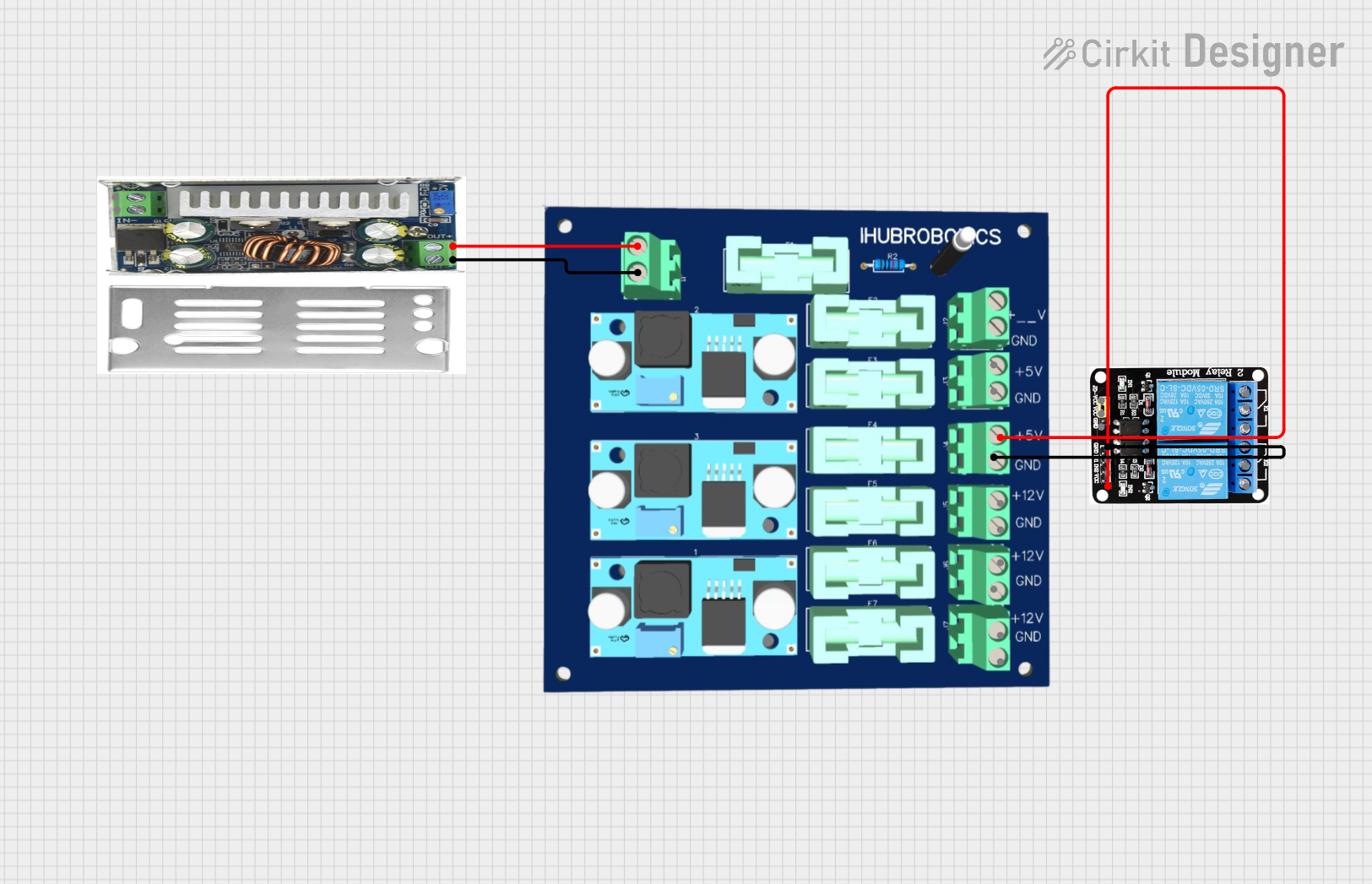
This circuit consists of a DC-DC converter powering a 6-channel power module, which in turn supplies 5V to a 2-relay module. The power module distributes the converted voltage to the relay module, enabling it to control external devices.
Open Project in Cirkit DesignerExplore Projects Built with vcc
High Voltage Generator with Push Switch Activation
This circuit features a high voltage generator connected to a terminal PCB for output, with its power supply controlled by a 2-pin push switch. The high voltage generator's VCC is connected through the switch, allowing the user to turn the high voltage output on and off. The circuit is powered by a 7.4V battery, with the positive terminal connected to the switch and the negative terminal connected to the generator's ground.
Open Project in Cirkit DesignerSolar Panel to 12V Battery Charging Circuit
This circuit connects a solar panel to a 12V battery for charging purposes. The positive terminal of the solar panel is connected to the VCC of the battery, and the negative terminal is connected to the GND of the battery, allowing for energy transfer from the solar panel to the battery.
Open Project in Cirkit DesignerCellular-Enabled IoT Device with Real-Time Clock and Power Management
This circuit features a LilyGo-SIM7000G module for cellular communication and GPS functionality, interfaced with an RTC DS3231 for real-time clock capabilities. It includes voltage sensing through two voltage sensor modules, and uses an 8-channel opto-coupler for isolating different parts of the circuit. Power management is handled by a buck converter connected to a DC power source and batteries, with a fuse for protection and a rocker switch for on/off control. Additionally, there's an LED for indication purposes.
Open Project in Cirkit DesignerDC-DC Converter and Relay Module Power Distribution System
This circuit consists of a DC-DC converter powering a 6-channel power module, which in turn supplies 5V to a 2-relay module. The power module distributes the converted voltage to the relay module, enabling it to control external devices.
Open Project in Cirkit DesignerTechnical Specifications
- Definition: Vcc refers to the positive supply voltage in a circuit. The exact value of Vcc depends on the circuit design and the components used.
- Typical Voltage Levels:
- 3.3V: Common in low-power devices and modern microcontrollers.
- 5V: Standard for many older microcontrollers and digital circuits.
- 12V or higher: Used in power-hungry devices or specific applications like motor drivers.
- Current Capacity: Determined by the power supply and the circuit's requirements.
Pin Configuration and Descriptions
Vcc is not a standalone component but rather a reference point or pin on many devices. Below is an example of how Vcc is typically represented in ICs or microcontrollers:
| Pin Name | Description | Typical Voltage |
|---|---|---|
| Vcc | Positive supply voltage for the circuit | 3.3V, 5V, or 12V |
| GND | Ground or 0V reference | 0V |
Usage Instructions
How to Use Vcc in a Circuit:
- Identify the voltage requirements of your components (e.g., 3.3V or 5V).
- Connect the Vcc pin of your components to the positive terminal of your power supply.
- Ensure that the ground (GND) of the power supply is connected to the circuit's ground.
Important Considerations:
- Always verify the voltage rating of your components to avoid damage.
- Use decoupling capacitors (e.g., 0.1µF ceramic capacitors) near the Vcc pin of ICs to filter noise and stabilize the supply voltage.
- Avoid exceeding the maximum current rating of your power supply to prevent overheating or failure.
Example: Connecting Vcc to an Arduino UNO: The Arduino UNO operates at 5V. Below is an example of powering an LED using the Arduino's Vcc pin:
// Example: Powering an LED using Arduino UNO's Vcc pin

// Define the pin connected to the LED
const int ledPin = 13; // Pin 13 is connected to the onboard LED

void setup() {
  pinMode(ledPin, OUTPUT); // Set the LED pin as an output
}

void loop() {
  digitalWrite(ledPin, HIGH); // Turn the LED on
  delay(1000);                // Wait for 1 second
  digitalWrite(ledPin, LOW);  // Turn the LED off
  delay(1000);                // Wait for 1 second
}
- In this example, the Arduino's onboard voltage regulator provides a stable 5V supply to the Vcc pin, which powers the LED.
Troubleshooting and FAQs
Common Issues:
- Component Overheating:
- Cause: Incorrect Vcc voltage or excessive current draw.
- Solution: Verify the voltage and current requirements of your components. Use a regulated power supply.
- Circuit Not Working:
- Cause: Loose or incorrect connections to the Vcc pin.
- Solution: Double-check all connections and ensure proper wiring.
- Noise or Instability:
- Cause: Insufficient decoupling or noisy power supply.
- Solution: Add decoupling capacitors near the Vcc pin and use a stable power source.
- Component Overheating:
FAQs:
- Can I use a 5V Vcc for a 3.3V component?
- No, exceeding the voltage rating of a component can damage it. Use a voltage regulator or level shifter to step down the voltage.
- What happens if Vcc and GND are swapped?
- Reversing Vcc and GND can permanently damage components. Always double-check polarity before powering the circuit.
- Why is my circuit not powering on?
- Check if the power supply is functioning, and ensure that Vcc and GND are properly connected to the circuit.
- Can I use a 5V Vcc for a 3.3V component?
By understanding and properly implementing Vcc in your circuits, you can ensure reliable and efficient operation of your electronic projects.