Cirkit Designer Logo
Cirkit Designer
Your all-in-one circuit design IDE
Home / 
Component Documentation

How to Use Adafruit STSPIN220 Stepper Motor Driver Breakout Board: Examples, Pinouts, and Specs

Image of Adafruit STSPIN220 Stepper Motor Driver Breakout Board
Cirkit Designer LogoDesign with Adafruit STSPIN220 Stepper Motor Driver Breakout Board in Cirkit Designer

Introduction

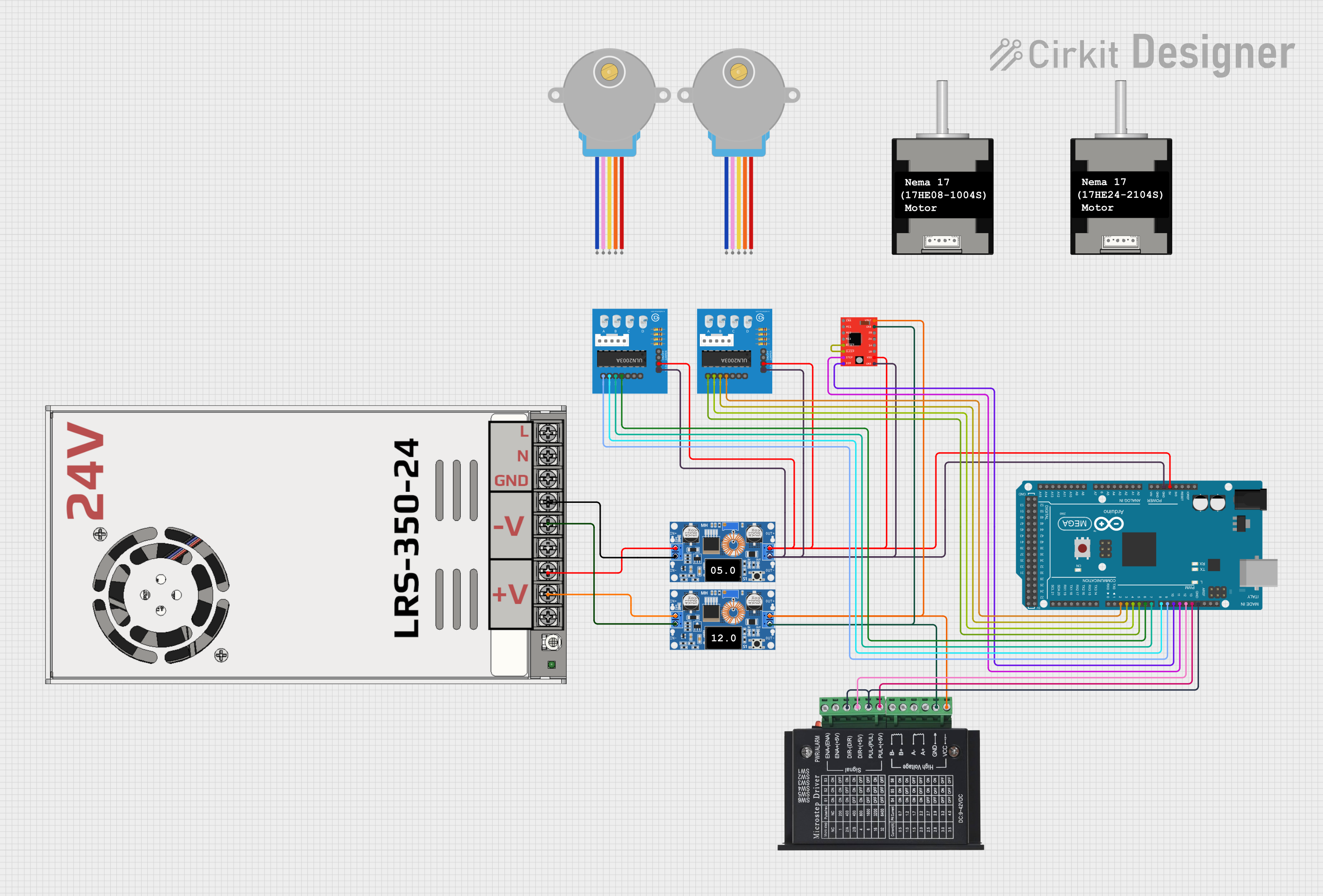
The Adafruit STSPIN220 Stepper Motor Driver Breakout Board (Manufacturer Part ID: 6353) is a compact and efficient stepper motor driver designed for precise control of stepper motors. It features adjustable current control, microstepping capabilities, and seamless integration with microcontrollers, making it ideal for a wide range of applications.

Explore Projects Built with Adafruit STSPIN220 Stepper Motor Driver Breakout Board

Use Cirkit Designer to design, explore, and prototype these projects online. Some projects support real-time simulation. Click "Open Project" to start designing instantly!
Teensy-Controlled Stepper Motor and Servo Actuation System
Image of Prototype Robotic Arm: A project utilizing Adafruit STSPIN220 Stepper Motor Driver Breakout Board in a practical application
This circuit controls a bipolar stepper motor using an A4988 Stepper Motor Driver, which is interfaced with a Teensy 4.1 microcontroller. The Teensy sends step and direction signals to the driver, while the driver's RESET and SLEEP pins are tied together, likely for simplified control. Additionally, the circuit includes an Adafruit PCA9685 PWM Servo Breakout board, which is connected to a servo motor and communicates with the Teensy via I2C, and both the driver and the breakout board are powered by separate power supplies with decoupling provided by an electrolytic capacitor.
Cirkit Designer LogoOpen Project in Cirkit Designer
Arduino UNO-Based Dual Stepper Motor Controller with Gesture Sensing and RTC Display
Image of Arduino UNO-Based Dual Stepper Motor Controller with Gesture Sensing and RTC Display: A project utilizing Adafruit STSPIN220 Stepper Motor Driver Breakout Board in a practical application
This circuit is an Arduino UNO-based dual stepper motor controller that uses ULN2003A driver boards to control two 28BYJ-48 stepper motors. It features an APDS-9960 RGB and gesture sensor for gesture-based control, a DS1307 RTC module to display time on a 16x2 I2C LCD, and includes a green LED and two pushbuttons for additional control and status indication.
Cirkit Designer LogoOpen Project in Cirkit Designer
Wi-Fi Controlled Environmental Monitoring System with Dual Stepper Motor Valve Actuation
Image of MVP : A project utilizing Adafruit STSPIN220 Stepper Motor Driver Breakout Board in a practical application
This circuit features two 28BYJ-48 stepper motors controlled by ULN2003A breakout boards, interfaced with a NodeMCU V3 ESP8266 microcontroller. The NodeMCU collects environmental data from a DHT11 temperature and humidity sensor and an MQ-135 air quality sensor. The microcontroller uses WiFi for connectivity and controls the stepper motors based on the sensor inputs, likely for regulating environmental conditions.
Cirkit Designer LogoOpen Project in Cirkit Designer
Arduino Mega 2560 Controlled Multi-Stepper Motor System with DC Buck Step-down Power Supply
Image of Arduino Mega 2560 Controlled Stepper Motor System with DC Buck Step-down Power Supply: A project utilizing Adafruit STSPIN220 Stepper Motor Driver Breakout Board in a practical application
This circuit is a stepper motor control system powered by a DC Buck Step-down power supply and controlled by an Arduino Mega 2560. It uses TB6600 and A4988 stepper motor drivers along with ULN2003A breakout boards to drive multiple stepper motors. The Arduino code initializes the pins and provides basic control functionality for the stepper motors.
Cirkit Designer LogoOpen Project in Cirkit Designer

Explore Projects Built with Adafruit STSPIN220 Stepper Motor Driver Breakout Board

Use Cirkit Designer to design, explore, and prototype these projects online. Some projects support real-time simulation. Click "Open Project" to start designing instantly!
Image of Prototype Robotic Arm: A project utilizing Adafruit STSPIN220 Stepper Motor Driver Breakout Board in a practical application
Teensy-Controlled Stepper Motor and Servo Actuation System
This circuit controls a bipolar stepper motor using an A4988 Stepper Motor Driver, which is interfaced with a Teensy 4.1 microcontroller. The Teensy sends step and direction signals to the driver, while the driver's RESET and SLEEP pins are tied together, likely for simplified control. Additionally, the circuit includes an Adafruit PCA9685 PWM Servo Breakout board, which is connected to a servo motor and communicates with the Teensy via I2C, and both the driver and the breakout board are powered by separate power supplies with decoupling provided by an electrolytic capacitor.
Cirkit Designer LogoOpen Project in Cirkit Designer
Image of Arduino UNO-Based Dual Stepper Motor Controller with Gesture Sensing and RTC Display: A project utilizing Adafruit STSPIN220 Stepper Motor Driver Breakout Board in a practical application
Arduino UNO-Based Dual Stepper Motor Controller with Gesture Sensing and RTC Display
This circuit is an Arduino UNO-based dual stepper motor controller that uses ULN2003A driver boards to control two 28BYJ-48 stepper motors. It features an APDS-9960 RGB and gesture sensor for gesture-based control, a DS1307 RTC module to display time on a 16x2 I2C LCD, and includes a green LED and two pushbuttons for additional control and status indication.
Cirkit Designer LogoOpen Project in Cirkit Designer
Image of MVP : A project utilizing Adafruit STSPIN220 Stepper Motor Driver Breakout Board in a practical application
Wi-Fi Controlled Environmental Monitoring System with Dual Stepper Motor Valve Actuation
This circuit features two 28BYJ-48 stepper motors controlled by ULN2003A breakout boards, interfaced with a NodeMCU V3 ESP8266 microcontroller. The NodeMCU collects environmental data from a DHT11 temperature and humidity sensor and an MQ-135 air quality sensor. The microcontroller uses WiFi for connectivity and controls the stepper motors based on the sensor inputs, likely for regulating environmental conditions.
Cirkit Designer LogoOpen Project in Cirkit Designer
Image of Arduino Mega 2560 Controlled Stepper Motor System with DC Buck Step-down Power Supply: A project utilizing Adafruit STSPIN220 Stepper Motor Driver Breakout Board in a practical application
Arduino Mega 2560 Controlled Multi-Stepper Motor System with DC Buck Step-down Power Supply
This circuit is a stepper motor control system powered by a DC Buck Step-down power supply and controlled by an Arduino Mega 2560. It uses TB6600 and A4988 stepper motor drivers along with ULN2003A breakout boards to drive multiple stepper motors. The Arduino code initializes the pins and provides basic control functionality for the stepper motors.
Cirkit Designer LogoOpen Project in Cirkit Designer

Common Applications and Use Cases

  • Robotics and automation systems
  • 3D printers and CNC machines
  • Camera sliders and gimbals
  • Precision positioning systems
  • DIY electronics and prototyping projects

Technical Specifications

The Adafruit STSPIN220 is built for high performance and flexibility. Below are its key technical details:

Parameter Value
Operating Voltage (Vcc) 3.0V to 10.0V
Motor Voltage (VM) 1.8V to 10.0V
Maximum Motor Current 1.3A RMS (1.8A peak)
Microstepping Modes Full-step, 1/2, 1/4, 1/8, 1/16, 1/32, 1/64, 1/128
Logic Voltage 3.3V or 5V compatible
Control Interface Step/Direction pins
Dimensions 20mm x 20mm x 4mm
Thermal Shutdown Yes
Overcurrent Protection Yes

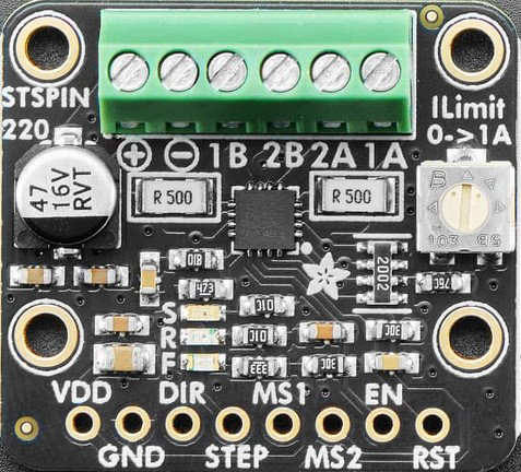
Pin Configuration and Descriptions

The breakout board has 10 pins, as described in the table below:

Pin Name Type Description
VIN Power Input Main power supply for the motor (1.8V to 10.0V).
GND Ground Ground connection for the motor and logic circuits.
VCC Power Input Logic voltage supply (3.0V to 10.0V).
STEP Input Step signal input for controlling motor steps.
DIR Input Direction signal input to set motor rotation direction.
ENABLE Input Enable/disable the motor driver (active low).
MODE0 Input Microstepping mode selection (see datasheet for mode combinations).
MODE1 Input Microstepping mode selection (see datasheet for mode combinations).
MODE2 Input Microstepping mode selection (see datasheet for mode combinations).
FAULT Output Fault indicator pin (active low when a fault occurs, e.g., overcurrent).

Usage Instructions

How to Use the Component in a Circuit

  1. Power Connections:

    • Connect the motor power supply to the VIN pin (1.8V to 10.0V).
    • Connect the logic power supply to the VCC pin (3.0V to 10.0V).
    • Ensure all grounds (GND) are connected.
  2. Control Signals:

    • Use the STEP pin to send pulses for each motor step.
    • Use the DIR pin to set the motor's rotation direction (HIGH for one direction, LOW for the other).
    • Set the ENABLE pin LOW to activate the driver and HIGH to disable it.
  3. Microstepping Configuration:

    • Configure the MODE0, MODE1, and MODE2 pins to select the desired microstepping mode. Refer to the datasheet for the specific pin combinations.
  4. Motor Connections:

    • Connect the stepper motor's two coils to the motor output terminals on the breakout board.
  5. Fault Monitoring:

    • Monitor the FAULT pin for any errors. If the pin goes LOW, check for issues such as overcurrent or thermal shutdown.

Important Considerations and Best Practices

  • Current Limiting: Adjust the current limit using the onboard potentiometer to match your motor's rated current. This prevents overheating and ensures optimal performance.
  • Power Supply: Use a stable power supply within the specified voltage range to avoid damage to the driver or motor.
  • Heat Dissipation: Ensure proper ventilation or add a heatsink if the driver operates at high currents for extended periods.
  • Signal Integrity: Use short and shielded wires for control signals to minimize noise and interference.

Example: Using with Arduino UNO

Below is an example of how to control the STSPIN220 with an Arduino UNO:

// Define pin connections
#define STEP_PIN 3    // Connect to STEP pin on STSPIN220
#define DIR_PIN 4     // Connect to DIR pin on STSPIN220
#define ENABLE_PIN 5  // Connect to ENABLE pin on STSPIN220

void setup() {
  // Set pin modes
  pinMode(STEP_PIN, OUTPUT);
  pinMode(DIR_PIN, OUTPUT);
  pinMode(ENABLE_PIN, OUTPUT);

  // Enable the motor driver
  digitalWrite(ENABLE_PIN, LOW); // LOW to enable the driver

  // Set initial direction
  digitalWrite(DIR_PIN, HIGH);  // HIGH for one direction, LOW for the other
}

void loop() {
  // Generate step pulses
  digitalWrite(STEP_PIN, HIGH); // Step pulse HIGH
  delayMicroseconds(500);       // Wait 500 microseconds
  digitalWrite(STEP_PIN, LOW);  // Step pulse LOW
  delayMicroseconds(500);       // Wait 500 microseconds
}

Troubleshooting and FAQs

Common Issues and Solutions

  1. Motor Not Moving:

    • Ensure the ENABLE pin is set to LOW.
    • Verify the STEP and DIR signals are being sent correctly.
    • Check the motor connections and ensure the coils are connected properly.
  2. Overheating:

    • Reduce the current limit using the onboard potentiometer.
    • Ensure proper ventilation or add a heatsink.
  3. FAULT Pin is LOW:

    • Check for overcurrent or thermal shutdown conditions.
    • Verify the power supply voltage is within the specified range.
  4. Motor Vibrates but Doesn't Rotate:

    • Verify the microstepping mode configuration.
    • Check the DIR signal and ensure it is set correctly.

FAQs

Q: Can I use a 12V power supply with this driver?
A: No, the maximum motor voltage (VIN) is 10.0V. Using a higher voltage may damage the driver.

Q: How do I set the microstepping mode?
A: Use the MODE0, MODE1, and MODE2 pins to configure the microstepping mode. Refer to the datasheet for the specific combinations.

Q: What happens if the motor draws more current than the limit?
A: The driver has built-in overcurrent protection and will shut down to prevent damage. Adjust the current limit to match your motor's specifications.

Q: Can I use this driver with a 5V logic microcontroller?
A: Yes, the STSPIN220 is compatible with both 3.3V and 5V logic levels.