How to Use step down converter: Examples, Pinouts, and Specs
Introduction
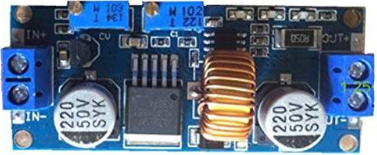
A step down converter, also known as a buck converter, is a DC-DC power converter that reduces a higher input voltage to a lower output voltage while increasing the current. It achieves this through the use of inductors, capacitors, and switches, ensuring efficient power conversion with minimal energy loss. Step down converters are widely used in applications where devices require a stable, lower voltage supply derived from a higher voltage source.
Explore Projects Built with step down converter


Explore Projects Built with step down converter
Common Applications and Use Cases
- Powering microcontrollers and sensors from higher voltage sources
- Battery-powered devices requiring efficient voltage regulation
- Voltage regulation in automotive and industrial systems
- Powering LEDs and other low-voltage components
- Renewable energy systems, such as solar charge controllers
Technical Specifications
Below are the general technical specifications for a typical step down converter. Note that specific models may vary, so always refer to the datasheet of the specific converter you are using.
Key Technical Details
- Input Voltage Range: 4.5V to 40V (varies by model)
- Output Voltage Range: 0.8V to 36V (adjustable or fixed)
- Output Current: Up to 3A or more (depending on the model)
- Efficiency: Up to 95% (depending on load and input/output conditions)
- Switching Frequency: 100kHz to 1MHz (varies by design)
- Operating Temperature: -40°C to +85°C (typical)
Pin Configuration and Descriptions
The pinout of a step down converter module (e.g., LM2596-based module) is as follows:
| Pin Name | Description |
|---|---|
| VIN | Input voltage pin. Connect the higher voltage source here. |
| GND | Ground pin. Connect to the ground of the circuit. |
| VOUT | Output voltage pin. Provides the stepped-down voltage to the load. |
| EN (optional) | Enable pin. Used to turn the converter on/off (active high). |
| ADJ (optional) | Adjustment pin. Used to set the output voltage (for adjustable converters). |
Usage Instructions
How to Use the Component in a Circuit
- Connect the Input Voltage:
- Connect the positive terminal of the input voltage source to the
VINpin. - Connect the negative terminal of the input voltage source to the
GNDpin.
- Connect the positive terminal of the input voltage source to the
- Set the Output Voltage (if adjustable):
- For adjustable step down converters, use the onboard potentiometer to set the desired output voltage. Use a multimeter to measure the output voltage at the
VOUTpin while adjusting.
- For adjustable step down converters, use the onboard potentiometer to set the desired output voltage. Use a multimeter to measure the output voltage at the
- Connect the Load:
- Connect the positive terminal of the load to the
VOUTpin. - Connect the negative terminal of the load to the
GNDpin.
- Connect the positive terminal of the load to the
- Enable the Converter (if applicable):
- If the module has an
ENpin, ensure it is connected to a high logic level (e.g., 5V) to enable the converter.
- If the module has an
Important Considerations and Best Practices
- Input Voltage: Ensure the input voltage is within the specified range of the converter. Exceeding the maximum input voltage can damage the module.
- Output Current: Do not exceed the maximum output current rating of the converter. Use a heatsink if necessary for high current loads.
- Filtering: Add input and output capacitors (if not already present on the module) to reduce voltage ripple and improve stability.
- Heat Dissipation: For high-power applications, ensure proper ventilation or use a heatsink to prevent overheating.
- Polarity: Double-check the polarity of the input and output connections to avoid damage.
Example: Using a Step Down Converter with Arduino UNO
Below is an example of how to use a step down converter to power an Arduino UNO from a 12V source:
- Connect the 12V source to the
VINandGNDpins of the step down converter. - Adjust the output voltage to 5V using the onboard potentiometer.
- Connect the
VOUTpin of the converter to the5Vpin of the Arduino UNO. - Connect the
GNDpin of the converter to theGNDpin of the Arduino UNO.
// Example Arduino code to blink an LED powered by a step down converter

int ledPin = 13; // Pin connected to the onboard LED

void setup() {
  pinMode(ledPin, OUTPUT); // Set the LED pin as an output
}

void loop() {
  digitalWrite(ledPin, HIGH); // Turn the LED on
  delay(1000);                // Wait for 1 second
  digitalWrite(ledPin, LOW);  // Turn the LED off
  delay(1000);                // Wait for 1 second
}
Troubleshooting and FAQs
Common Issues and Solutions
No Output Voltage:
- Check the input voltage and ensure it is within the specified range.
- Verify that the
ENpin is set to a high logic level (if applicable). - Inspect the connections for loose wires or incorrect polarity.
Output Voltage is Incorrect:
- For adjustable converters, recheck the potentiometer setting and adjust as needed.
- Ensure the load is not drawing more current than the converter's maximum rating.
Excessive Heat:
- Verify that the input and output voltages are within the specified range.
- Use a heatsink or improve ventilation if the converter is operating at high power levels.
High Voltage Ripple:
- Add additional input and output capacitors to reduce ripple.
- Ensure the load is stable and not causing sudden current spikes.
FAQs
Q: Can I use a step down converter to power a Raspberry Pi?
A: Yes, you can use a step down converter to power a Raspberry Pi. Ensure the output voltage is set to 5V and the converter can supply at least 2.5A for stable operation.
Q: What happens if I reverse the input polarity?
A: Most step down converters do not have reverse polarity protection. Reversing the input polarity can damage the module. Always double-check your connections.
Q: Can I use a step down converter with an AC input?
A: No, step down converters are designed for DC input only. Use a rectifier and filter circuit to convert AC to DC before using the converter.
Q: How do I calculate the efficiency of the converter?
A: Efficiency can be calculated using the formula:
[
\text{Efficiency} (%) = \left( \frac{\text{Output Power}}{\text{Input Power}} \right) \times 100
]
Measure the input and output voltages and currents to determine the power values.