How to Use SSR: Examples, Pinouts, and Specs
Introduction
A Solid State Relay (SSR) is an electronic switching device that uses semiconductor components, such as thyristors, triacs, or transistors, to perform switching operations. Unlike traditional electromechanical relays, SSRs have no moving parts, which allows for faster switching speeds, silent operation, and a significantly longer lifespan. SSRs are ideal for applications requiring high reliability and frequent switching.
Explore Projects Built with SSR


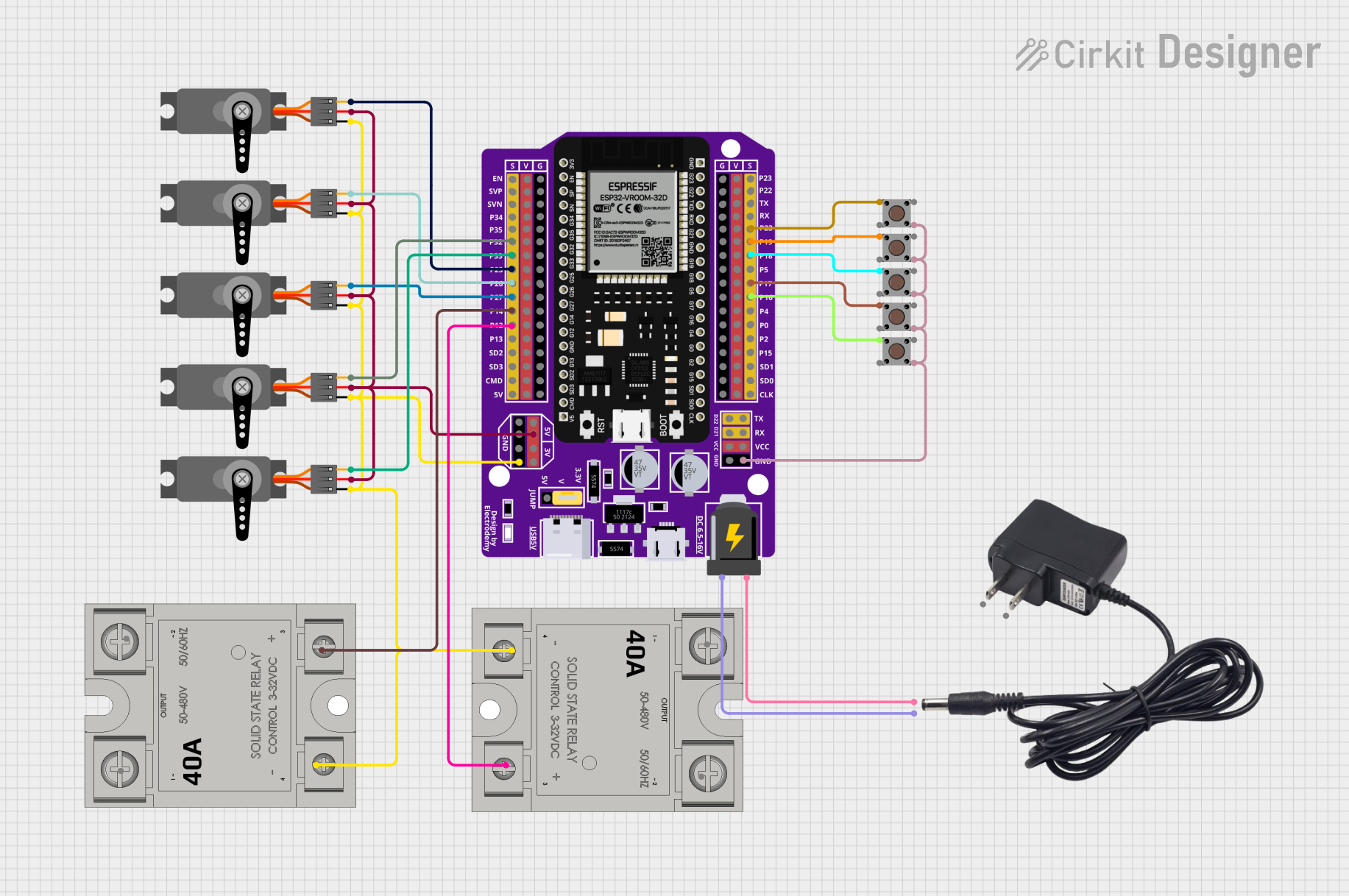
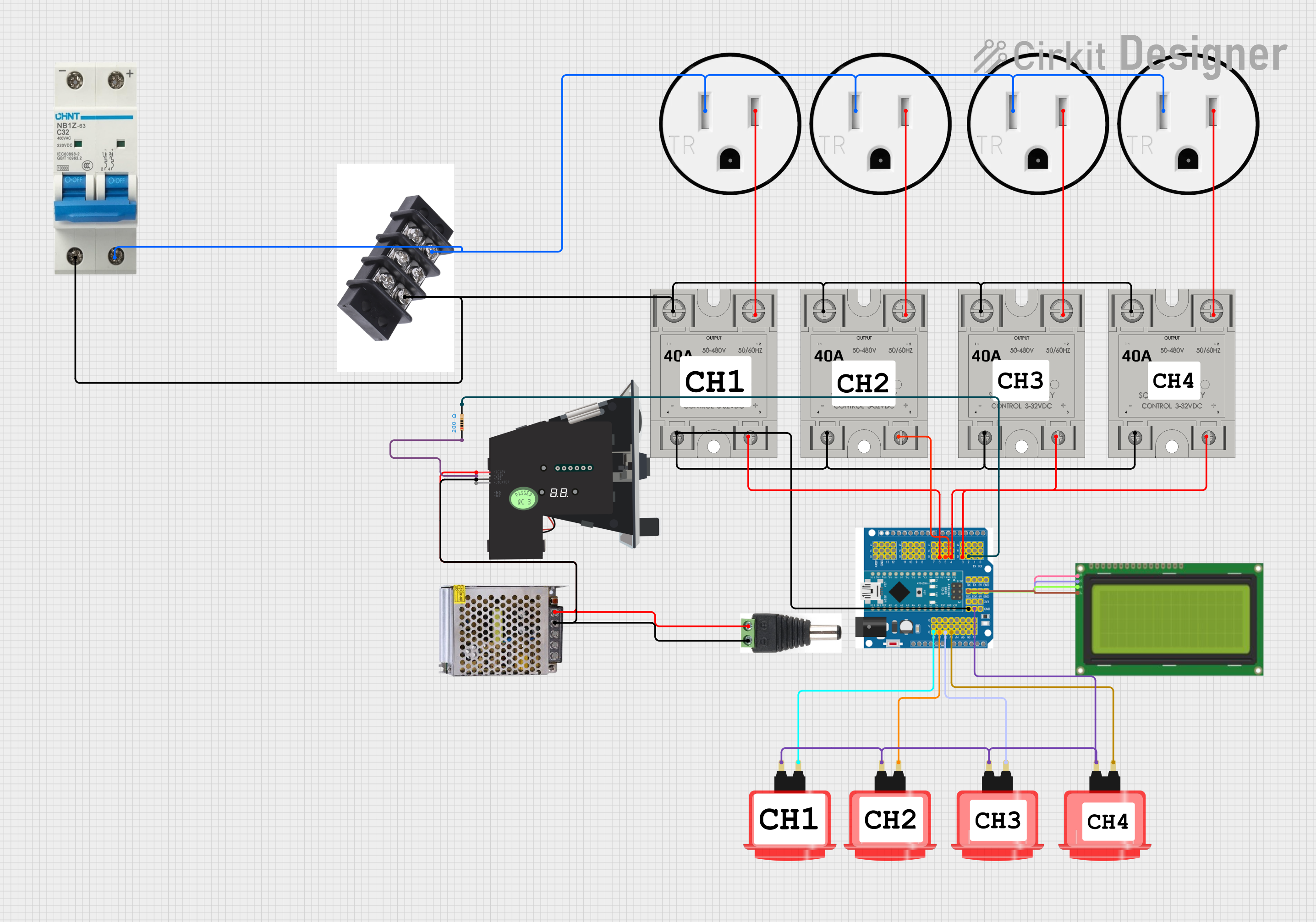
Explore Projects Built with SSR
Common Applications and Use Cases
- Industrial automation and control systems
- Heating, ventilation, and air conditioning (HVAC) systems
- Motor control and speed regulation
- Lighting control systems
- Home appliances and smart home devices
- Temperature control in ovens and furnaces
Technical Specifications
Key Technical Details
| Parameter | Value/Range |
|---|---|
| Input Control Voltage | 3-32 VDC (typical, varies by model) |
| Output Voltage Range | 24-480 VAC (typical, varies by model) |
| Output Current Rating | 2-100 A (depending on model) |
| Switching Speed | < 1 ms |
| Isolation Voltage | 2500-4000 V (varies by model) |
| Operating Temperature | -30°C to +80°C |
| Dielectric Strength | 2.5 kV RMS |
| Mounting Style | Panel or DIN rail |
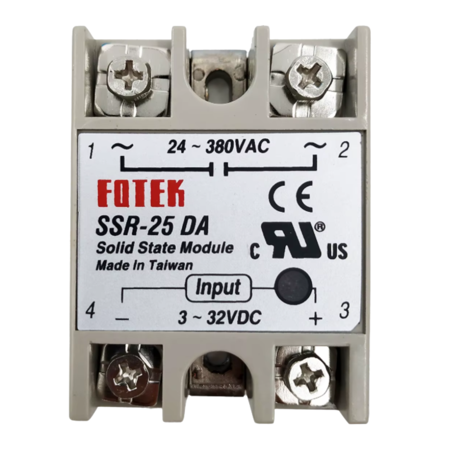
Pin Configuration and Descriptions
The pin configuration of an SSR typically includes input control terminals and output load terminals. Below is a general description:
| Pin Name | Description |
|---|---|
| Input (+) | Positive terminal for the control signal (e.g., from a microcontroller). |
| Input (-) | Negative terminal for the control signal (ground). |
| Output (Load+) | Positive terminal for the AC load connection. |
| Output (Load-) | Negative terminal for the AC load connection. |
Note: The exact pin configuration may vary depending on the SSR model. Always refer to the manufacturer's datasheet for specific details.
Usage Instructions
How to Use the Component in a Circuit
- Control Signal Connection: Connect the input terminals of the SSR to the control signal source, such as a microcontroller (e.g., Arduino UNO) or a DC power supply. Ensure the control voltage is within the specified range for the SSR.
- Load Connection: Connect the AC load (e.g., motor, heater, or light) to the output terminals of the SSR. Ensure the load voltage and current are within the SSR's rated capacity.
- Power Supply: Ensure the SSR is powered correctly and that the load circuit is properly grounded.
- Switching: When the control signal is applied, the SSR will switch the load circuit on. Removing the control signal will turn the load circuit off.
Important Considerations and Best Practices
- Heat Dissipation: SSRs generate heat during operation. Use a heat sink or proper ventilation to prevent overheating.
- Snubber Circuit: For inductive loads, use a snubber circuit to suppress voltage spikes and protect the SSR.
- Isolation: Ensure proper electrical isolation between the control and load circuits to prevent damage to sensitive components.
- Load Compatibility: Verify that the SSR's output voltage and current ratings match the load requirements.
- Polarity: Observe correct polarity when connecting the control signal to avoid damage to the SSR.
Example: Connecting an SSR to an Arduino UNO
Below is an example of how to control an SSR using an Arduino UNO to switch an AC load.
Circuit Diagram
- Connect the SSR's input (+) terminal to an Arduino digital output pin (e.g., pin 9).
- Connect the SSR's input (-) terminal to the Arduino GND.
- Connect the AC load to the SSR's output terminals as per the SSR's datasheet.
Arduino Code
// Example code to control an SSR with an Arduino UNO
// This code toggles the SSR on and off every 2 seconds

#define SSR_PIN 9  // Define the digital pin connected to the SSR

void setup() {
  pinMode(SSR_PIN, OUTPUT);  // Set the SSR pin as an output
}

void loop() {
  digitalWrite(SSR_PIN, HIGH);  // Turn the SSR on (AC load powered)
  delay(2000);                  // Wait for 2 seconds
  digitalWrite(SSR_PIN, LOW);   // Turn the SSR off (AC load off)
  delay(2000);                  // Wait for 2 seconds
}
Note: Ensure proper safety precautions when working with AC loads. Disconnect power before making any connections.
Troubleshooting and FAQs
Common Issues and Solutions
| Issue | Possible Cause | Solution |
|---|---|---|
| SSR does not switch the load | Insufficient control voltage/current | Verify the control signal meets SSR specs. |
| Load does not turn off | Leakage current in SSR | Use a load resistor to dissipate leakage. |
| SSR overheats | Inadequate heat dissipation | Add a heat sink or improve ventilation. |
| Flickering or unstable operation | Noise or interference in control signal | Use a decoupling capacitor on the input. |
| SSR fails to operate | Incorrect wiring or damaged SSR | Double-check connections and replace SSR. |
FAQs
Can an SSR switch DC loads?
- Most SSRs are designed for AC loads. For DC loads, use an SSR specifically rated for DC operation.
Why is there a small voltage across the load when the SSR is off?
- SSRs have a small leakage current when off. This is normal and can be mitigated with a load resistor.
How do I protect the SSR from voltage spikes?
- Use a snubber circuit or a varistor across the output terminals to suppress voltage spikes.
Can I use an SSR for high-frequency switching?
- Yes, SSRs are suitable for high-frequency switching due to their fast response time.
What happens if the load exceeds the SSR's current rating?
- Exceeding the current rating can damage the SSR. Always choose an SSR with a current rating higher than the load's maximum current.
By following this documentation, you can effectively integrate and troubleshoot a Solid State Relay in your electronic projects.