How to Use PLC SCHNEIDER TM221CE40R: Examples, Pinouts, and Specs
Introduction
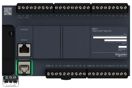
The Schneider TM221CE40R is a programmable logic controller (PLC) designed for automation and control applications. It features a compact design, integrated I/O (Input/Output), and supports various communication protocols, making it suitable for small to medium-sized industrial tasks. This PLC is part of Schneider Electric's Modicon M221 series, known for its reliability, flexibility, and ease of use.
Explore Projects Built with PLC SCHNEIDER TM221CE40R


Explore Projects Built with PLC SCHNEIDER TM221CE40R
Common Applications and Use Cases
- Industrial automation and process control
- Machine control in manufacturing environments
- Building automation systems
- Conveyor belt systems
- Packaging machinery
- Energy management and monitoring
Technical Specifications
Key Technical Details
| Specification | Value |
|---|---|
| Model | TM221CE40R |
| Supply Voltage | 24 V DC |
| Number of Digital Inputs | 24 |
| Number of Digital Outputs | 16 (Relay outputs) |
| Communication Protocols | Ethernet, Modbus TCP, Serial (RS485) |
| Programming Software | EcoStruxure Machine Expert - Basic |
| Memory | 256 KB for application storage |
| Operating Temperature Range | -10°C to +55°C |
| Dimensions | 95 x 90 x 70 mm |
| Mounting | DIN Rail |
Pin Configuration and Descriptions
The TM221CE40R features multiple I/O terminals for connecting sensors, actuators, and other devices. Below is the pin configuration:
Digital Inputs
| Pin Number | Description | Voltage Range |
|---|---|---|
| I0 - I23 | Digital Inputs (24 channels) | 0-24 V DC |
Digital Outputs
| Pin Number | Description | Output Type |
|---|---|---|
| Q0 - Q15 | Digital Outputs (16 channels) | Relay (NO/NC) |
Communication Ports
| Port Name | Description | Protocol Supported |
|---|---|---|
| Ethernet | Ethernet Communication Port | Modbus TCP |
| Serial | RS485 Communication Port | Modbus RTU |
Usage Instructions
How to Use the TM221CE40R in a Circuit
- Power Supply: Connect a 24 V DC power supply to the PLC's power input terminals.
- Digital Inputs: Wire sensors or switches to the digital input terminals (I0-I23). Ensure the input voltage does not exceed 24 V DC.
- Digital Outputs: Connect actuators, relays, or other devices to the digital output terminals (Q0-Q15). Verify the output current and voltage ratings of the connected devices.
- Communication: Use the Ethernet or RS485 port to connect the PLC to a network or other devices for communication. Configure the communication settings in the EcoStruxure Machine Expert - Basic software.
- Programming: Write and upload your control logic using the EcoStruxure Machine Expert - Basic software. The software supports ladder logic, function block diagrams, and structured text programming languages.
Important Considerations and Best Practices
- Always verify the power supply voltage and polarity before powering the PLC.
- Use proper shielding and grounding for communication cables to avoid interference.
- Ensure that the total current drawn by the outputs does not exceed the PLC's maximum output current rating.
- Regularly back up your PLC program to avoid data loss.
- Follow the manufacturer's guidelines for installation and maintenance.
Example Code for Modbus Communication with Arduino UNO
Below is an example of how to connect the TM221CE40R to an Arduino UNO using Modbus RTU over RS485:
#include <ModbusMaster.h>

// Instantiate ModbusMaster object
ModbusMaster node;

void setup() {
  Serial.begin(9600); // Initialize serial communication
  node.begin(1, Serial); // Set Modbus slave ID to 1
}

void loop() {
  uint8_t result;
  uint16_t data;

  // Read a holding register (e.g., register 40001)
  result = node.readHoldingRegisters(0x0000, 1);

  if (result == node.ku8MBSuccess) {
    data = node.getResponseBuffer(0); // Get the data from the register
    Serial.print("Register Value: ");
    Serial.println(data);
  } else {
    Serial.println("Failed to read register");
  }

  delay(1000); // Wait 1 second before the next read
}
Note: Use an RS485 module to connect the Arduino UNO to the TM221CE40R. Ensure proper wiring and termination resistors for reliable communication.
Troubleshooting and FAQs
Common Issues and Solutions
PLC Not Powering On
- Cause: Incorrect power supply voltage or polarity.
- Solution: Verify the power supply voltage is 24 V DC and check the polarity.
Inputs Not Responding
- Cause: Faulty wiring or incorrect input voltage.
- Solution: Check the wiring and ensure the input voltage is within the specified range (0-24 V DC).
Outputs Not Activating
- Cause: Overloaded output or incorrect wiring.
- Solution: Verify the connected load does not exceed the output's current rating. Check the wiring.
Communication Failure
- Cause: Incorrect communication settings or faulty cables.
- Solution: Ensure the baud rate, parity, and other settings match between devices. Use shielded cables and check for loose connections.
Program Upload Fails
- Cause: Incorrect PLC connection or software configuration.
- Solution: Verify the PLC is properly connected to the PC and the correct COM port is selected in the software.
FAQs
Q: Can the TM221CE40R be used in high-temperature environments?
A: The operating temperature range is -10°C to +55°C. For higher temperatures, additional cooling or ventilation may be required.
Q: What software is required to program the TM221CE40R?
A: The PLC is programmed using Schneider Electric's EcoStruxure Machine Expert - Basic software.
Q: Does the TM221CE40R support analog inputs/outputs?
A: No, the TM221CE40R only supports digital inputs and outputs. For analog I/O, consider other models in the Modicon M221 series.
Q: Can I connect the TM221CE40R to an HMI?
A: Yes, the PLC supports communication with HMIs via Modbus TCP or Modbus RTU protocols.
Q: How do I reset the PLC to factory settings?
A: Refer to the user manual for detailed instructions on performing a factory reset. Typically, this involves using the hardware reset button or software tools.