How to Use 60x60x20 Fan 24V: Examples, Pinouts, and Specs
Introduction
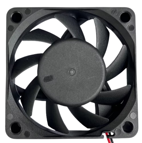
The 60x60x20 Fan 24V is a compact cooling fan with dimensions of 60mm x 60mm x 20mm. It operates at a voltage of 24V and is commonly used for cooling electronic components or enclosures. This fan is ideal for applications where space is limited but efficient cooling is required.
Explore Projects Built with 60x60x20 Fan 24V


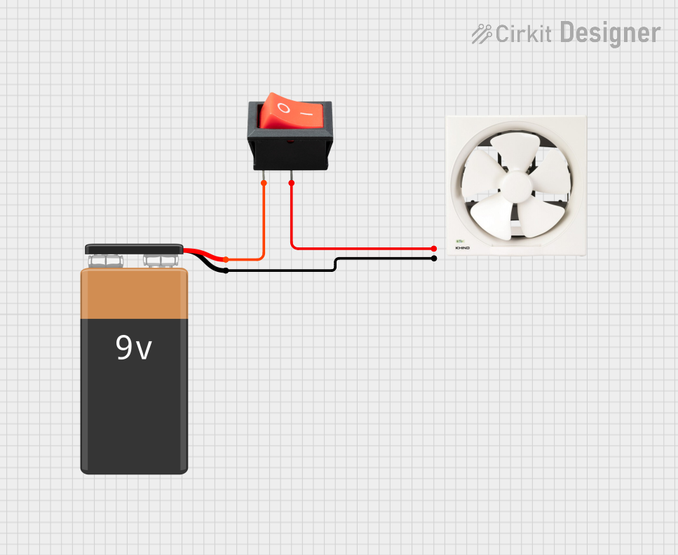
Explore Projects Built with 60x60x20 Fan 24V
Common Applications and Use Cases
- Cooling electronic components such as CPUs, GPUs, and power supplies
- Ventilating enclosures and cabinets
- Enhancing airflow in 3D printers
- Cooling for industrial equipment and machinery
Technical Specifications
Key Technical Details
| Parameter | Value |
|---|---|
| Dimensions | 60mm x 60mm x 20mm |
| Operating Voltage | 24V DC |
| Current Rating | 0.1A |
| Power Consumption | 2.4W |
| Airflow | 20 CFM |
| Noise Level | 30 dBA |
| Bearing Type | Sleeve Bearing |
| Connector Type | 2-pin JST |
Pin Configuration and Descriptions
| Pin Number | Pin Name | Description |
|---|---|---|
| 1 | VCC | Positive power supply (24V) |
| 2 | GND | Ground |
Usage Instructions
How to Use the Component in a Circuit
- Power Supply: Ensure you have a 24V DC power supply to power the fan.
- Connections: Connect the VCC pin of the fan to the positive terminal of the power supply and the GND pin to the ground terminal.
- Mounting: Secure the fan in place using screws or adhesive, ensuring it is positioned to maximize airflow over the components you wish to cool.
Important Considerations and Best Practices
- Voltage: Do not exceed the 24V operating voltage to avoid damaging the fan.
- Orientation: Install the fan in the correct orientation to ensure optimal airflow.
- Noise: Be aware of the noise level (30 dBA) if using the fan in noise-sensitive environments.
- Maintenance: Periodically clean the fan to prevent dust buildup, which can reduce efficiency and lifespan.
Troubleshooting and FAQs
Common Issues Users Might Face
Fan Not Spinning
- Solution: Check the power supply to ensure it is providing 24V. Verify the connections to the VCC and GND pins.
Excessive Noise
- Solution: Ensure the fan is securely mounted and not vibrating against other components. Clean any dust or debris from the fan blades.
Insufficient Cooling
- Solution: Verify that the fan is correctly oriented and that there are no obstructions to airflow. Consider using additional fans if necessary.
FAQs
Q: Can I use this fan with an Arduino UNO? A: Yes, but you will need an external 24V power supply. The Arduino UNO cannot directly power the fan due to its voltage limitations.
Q: How do I control the fan speed with an Arduino? A: You can use a transistor or MOSFET to control the fan speed via PWM (Pulse Width Modulation) from the Arduino. Below is an example code snippet for controlling the fan speed using an N-channel MOSFET:
// Define the pin connected to the MOSFET gate
const int fanPin = 9;

void setup() {
  // Set the fan pin as an output
  pinMode(fanPin, OUTPUT);
}

void loop() {
  // Set fan speed to 50% using PWM
  analogWrite(fanPin, 128); // 128 is 50% of 255
  delay(5000); // Run at 50% speed for 5 seconds

  // Set fan speed to 100% using PWM
  analogWrite(fanPin, 255); // 255 is 100% of 255
  delay(5000); // Run at 100% speed for 5 seconds
}
Q: What is the lifespan of this fan? A: The lifespan of the fan depends on usage and environmental conditions. Regular maintenance, such as cleaning dust from the blades, can help extend its lifespan.
By following this documentation, users can effectively utilize the 60x60x20 Fan 24V in their projects, ensuring optimal cooling and performance.