How to Use ESP32 CH340: Examples, Pinouts, and Specs
Introduction
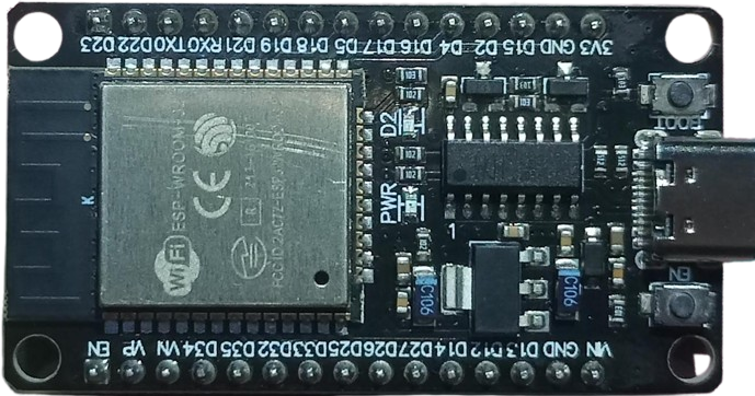
The ESP32 CH340 is a versatile microcontroller module developed by Espressif Systems. It combines the powerful ESP32 microcontroller with the CH340 USB-to-serial converter, enabling seamless communication between the module and a computer via USB. The ESP32 is known for its dual-core processor, integrated Wi-Fi, and Bluetooth capabilities, making it ideal for IoT (Internet of Things) applications, smart devices, and wireless communication projects.
The CH340 chip simplifies USB connectivity, allowing users to program and debug the ESP32 module easily. This combination makes the ESP32 CH340 a popular choice for hobbyists, developers, and engineers working on wireless and IoT projects.
Explore Projects Built with ESP32 CH340

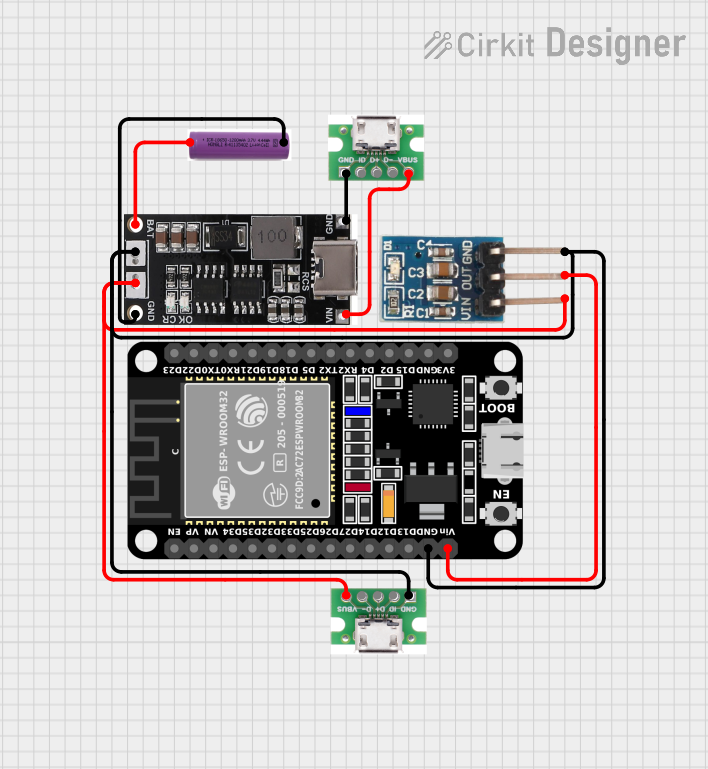

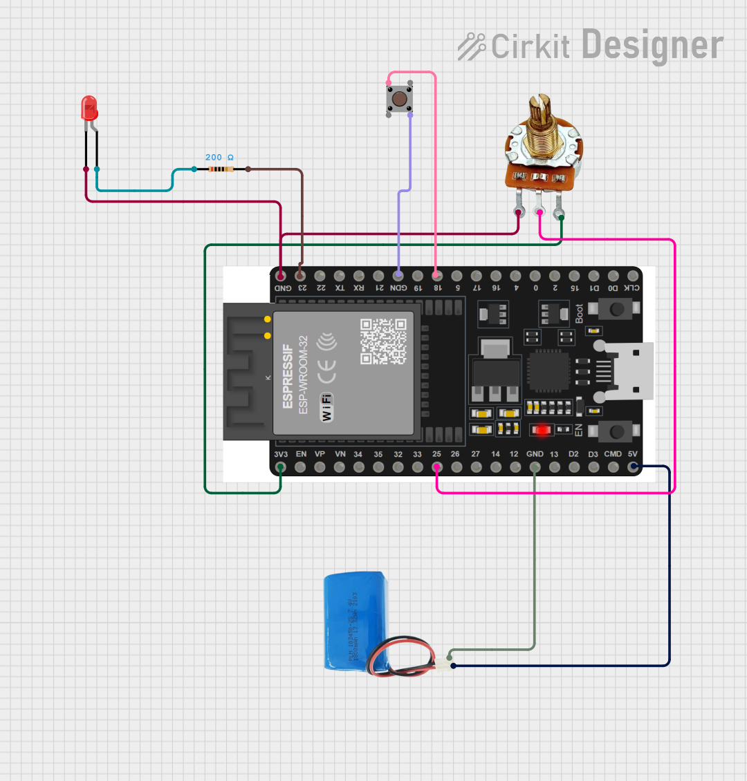
Explore Projects Built with ESP32 CH340
Common Applications and Use Cases
- IoT devices and smart home automation
- Wireless sensor networks
- Bluetooth-enabled devices
- Robotics and automation systems
- Prototyping and development of Wi-Fi/Bluetooth applications
Technical Specifications
Key Technical Details
| Parameter | Specification |
|---|---|
| Microcontroller | ESP32 (dual-core Xtensa LX6 processor) |
| Clock Speed | Up to 240 MHz |
| Flash Memory | Typically 4 MB (varies by module version) |
| SRAM | 520 KB |
| Wireless Connectivity | Wi-Fi 802.11 b/g/n, Bluetooth v4.2 + BLE |
| USB-to-Serial Converter | CH340 |
| Operating Voltage | 3.3V |
| Input Voltage (VIN) | 5V (via USB or external power supply) |
| GPIO Pins | 34 (multipurpose, including ADC, DAC, PWM, etc.) |
| Communication Interfaces | UART, SPI, I2C, I2S, CAN, Ethernet MAC |
| ADC Resolution | 12-bit |
| DAC Resolution | 8-bit |
| Operating Temperature | -40°C to 85°C |
Pin Configuration and Descriptions
| Pin Name | Description |
|---|---|
| VIN | Input voltage (5V) for powering the module via an external power source. |
| 3V3 | Regulated 3.3V output from the onboard voltage regulator. |
| GND | Ground pin. |
| EN | Enable pin. Pulling this pin low disables the module. |
| GPIO0 | General-purpose I/O pin, also used for boot mode selection. |
| GPIO1 | General-purpose I/O pin, typically used as UART TX. |
| GPIO3 | General-purpose I/O pin, typically used as UART RX. |
| GPIO34 | Input-only GPIO pin. |
| ADCx | Analog-to-digital converter input pins (e.g., ADC1_0, ADC1_1, etc.). |
| DACx | Digital-to-analog converter output pins (e.g., DAC1, DAC2). |
Note: The exact pinout may vary depending on the specific ESP32 CH340 module version. Refer to the module's datasheet for detailed pin mappings.
Usage Instructions
How to Use the ESP32 CH340 in a Circuit
Powering the Module:
- Connect the module to a computer or USB power source using a micro-USB cable. The CH340 chip will handle USB-to-serial communication.
- Alternatively, supply 5V to the VIN pin and connect GND to the ground of your power source.
Programming the Module:
- Install the CH340 driver on your computer (available for Windows, macOS, and Linux).
- Use the Arduino IDE or Espressif's ESP-IDF to write and upload code to the ESP32.
- Select the correct board (e.g., "ESP32 Dev Module") and COM port in the Arduino IDE.
Connecting Peripherals:
- Use GPIO pins to connect sensors, actuators, or other peripherals.
- For analog inputs, connect sensors to ADC pins. For PWM outputs, use GPIO pins with PWM functionality.
Wi-Fi and Bluetooth Setup:
- Use the ESP32's built-in libraries to configure Wi-Fi and Bluetooth. For example, use the
WiFilibrary to connect to a network.
- Use the ESP32's built-in libraries to configure Wi-Fi and Bluetooth. For example, use the
Important Considerations and Best Practices
- Voltage Levels: Ensure that all connected peripherals operate at 3.3V logic levels to avoid damaging the ESP32.
- Boot Mode: To enter bootloader mode, hold the "BOOT" button while pressing the "EN" (reset) button.
- Heat Management: The ESP32 may heat up during operation. Ensure proper ventilation or use a heatsink if necessary.
- Driver Installation: Install the CH340 driver before connecting the module to your computer to avoid communication issues.
Example Code for Arduino UNO Integration
Below is an example of using the ESP32 CH340 to connect to a Wi-Fi network and send data to a server:
#include <WiFi.h> // Include the Wi-Fi library

// Replace with your network credentials
const char* ssid = "Your_SSID";
const char* password = "Your_PASSWORD";

void setup() {
  Serial.begin(115200); // Initialize serial communication
  delay(1000);

  // Connect to Wi-Fi
  Serial.print("Connecting to Wi-Fi");
  WiFi.begin(ssid, password);
  while (WiFi.status() != WL_CONNECTED) {
    delay(500);
    Serial.print(".");
  }
  Serial.println("\nWi-Fi connected!");
  Serial.print("IP Address: ");
  Serial.println(WiFi.localIP()); // Print the device's IP address
}

void loop() {
  // Example: Send data to a server or perform other tasks
  delay(1000); // Placeholder for main loop code
}
Note: Replace
Your_SSIDandYour_PASSWORDwith your Wi-Fi network's credentials.
Troubleshooting and FAQs
Common Issues and Solutions
ESP32 Not Detected by Computer:
- Ensure the CH340 driver is installed correctly.
- Try a different USB cable or port.
- Verify that the module is powered on.
Upload Fails in Arduino IDE:
- Check that the correct board and COM port are selected.
- Hold the "BOOT" button while uploading the code.
Wi-Fi Connection Issues:
- Double-check the SSID and password.
- Ensure the Wi-Fi network is within range and operational.
Overheating:
- Avoid overloading the GPIO pins.
- Use proper ventilation or a heatsink if the module gets too hot.
FAQs
Q: Can the ESP32 CH340 operate at 5V logic levels?
A: No, the ESP32 operates at 3.3V logic levels. Use a level shifter if interfacing with 5V devices.Q: How do I reset the ESP32?
A: Press the "EN" button on the module to reset it.Q: Is the CH340 driver required for all operating systems?
A: Yes, the CH340 driver must be installed for the module to communicate with your computer.
By following this documentation, users can effectively utilize the ESP32 CH340 for a wide range of applications.