Cirkit Designer Logo
Cirkit Designer
Your all-in-one circuit design IDE
Home / 
Component Documentation

How to Use Diode 1N5822: Examples, Pinouts, and Specs

Image of Diode 1N5822
Cirkit Designer LogoDesign with Diode 1N5822 in Cirkit Designer

Introduction

The 1N5822 is a Schottky diode designed for high-efficiency power applications. It is characterized by its low forward voltage drop (typically 0.525V at 3A) and fast switching speed, which minimizes power loss and heat generation. These features make it an excellent choice for use in power rectification, voltage clamping, freewheeling diodes in DC-DC converters, and reverse polarity protection circuits.

Explore Projects Built with Diode 1N5822

Use Cirkit Designer to design, explore, and prototype these projects online. Some projects support real-time simulation. Click "Open Project" to start designing instantly!
Piezo Sensor-Based LED Indicator with Pushbutton Control
Image of project: A project utilizing Diode 1N5822 in a practical application
This circuit is a rectifier and indicator system that uses multiple 1N4007 diodes to rectify an AC signal, a piezo sensor for signal detection, and a pushbutton to control the circuit. The rectified signal is filtered by an electrolytic capacitor and a resistor, and the presence of the signal is indicated by a blue LED.
Cirkit Designer LogoOpen Project in Cirkit Designer
Diode and Capacitor-Based Voltage Regulation Circuit
Image of Pavetra#2: A project utilizing Diode 1N5822 in a practical application
This circuit is a complex network of diodes and electrolytic capacitors connected to two terminal PCB 2-pin connectors. The diodes are arranged in a series-parallel configuration, while the capacitors are connected in a manner that suggests filtering or energy storage purposes. The overall design appears to be aimed at rectification and smoothing of an input signal.
Cirkit Designer LogoOpen Project in Cirkit Designer
Voltage Regulated Transformer Power Supply Circuit
Image of revisi 3 : A project utilizing Diode 1N5822 in a practical application
This circuit appears to be a power supply circuit with a transformer connected to a 12V battery for voltage step-up or step-down. It includes a rectification stage with a 1N4007 diode, smoothing with an electrolytic capacitor, and regulation using a Zener diode. Additionally, there are inductors for filtering and a BT139 600 triac for controlling AC power, possibly for dimming or switching applications.
Cirkit Designer LogoOpen Project in Cirkit Designer
Rectifier Diode and LED Circuit with Rocker Switch Control
Image of hypihygi innovations: A project utilizing Diode 1N5822 in a practical application
This circuit appears to be a simple power supply circuit with a protection diode and an LED indicator. The diode ensures current flows in only one direction, protecting the circuit from reverse polarity damage. A rocker switch is used to control the power to the LED, which likely serves as an indicator for when the power is on.
Cirkit Designer LogoOpen Project in Cirkit Designer

Explore Projects Built with Diode 1N5822

Use Cirkit Designer to design, explore, and prototype these projects online. Some projects support real-time simulation. Click "Open Project" to start designing instantly!
Image of project: A project utilizing Diode 1N5822 in a practical application
Piezo Sensor-Based LED Indicator with Pushbutton Control
This circuit is a rectifier and indicator system that uses multiple 1N4007 diodes to rectify an AC signal, a piezo sensor for signal detection, and a pushbutton to control the circuit. The rectified signal is filtered by an electrolytic capacitor and a resistor, and the presence of the signal is indicated by a blue LED.
Cirkit Designer LogoOpen Project in Cirkit Designer
Image of Pavetra#2: A project utilizing Diode 1N5822 in a practical application
Diode and Capacitor-Based Voltage Regulation Circuit
This circuit is a complex network of diodes and electrolytic capacitors connected to two terminal PCB 2-pin connectors. The diodes are arranged in a series-parallel configuration, while the capacitors are connected in a manner that suggests filtering or energy storage purposes. The overall design appears to be aimed at rectification and smoothing of an input signal.
Cirkit Designer LogoOpen Project in Cirkit Designer
Image of revisi 3 : A project utilizing Diode 1N5822 in a practical application
Voltage Regulated Transformer Power Supply Circuit
This circuit appears to be a power supply circuit with a transformer connected to a 12V battery for voltage step-up or step-down. It includes a rectification stage with a 1N4007 diode, smoothing with an electrolytic capacitor, and regulation using a Zener diode. Additionally, there are inductors for filtering and a BT139 600 triac for controlling AC power, possibly for dimming or switching applications.
Cirkit Designer LogoOpen Project in Cirkit Designer
Image of hypihygi innovations: A project utilizing Diode 1N5822 in a practical application
Rectifier Diode and LED Circuit with Rocker Switch Control
This circuit appears to be a simple power supply circuit with a protection diode and an LED indicator. The diode ensures current flows in only one direction, protecting the circuit from reverse polarity damage. A rocker switch is used to control the power to the LED, which likely serves as an indicator for when the power is on.
Cirkit Designer LogoOpen Project in Cirkit Designer

Common Applications

  • Power supply rectification (AC to DC conversion)
  • Voltage clamping in sensitive circuits
  • Freewheeling diodes in motor drivers and DC-DC converters
  • Reverse polarity protection in battery-powered devices
  • Solar panel and battery charging systems

Technical Specifications

Key Specifications

Parameter Value
Maximum Repetitive Peak Reverse Voltage (VRRM) 40V
Maximum Average Forward Current (IF(AV)) 3A
Maximum Forward Voltage Drop (VF) 0.525V at 3A
Maximum Reverse Current (IR) 1mA at 40V
Operating Temperature Range -65°C to +150°C
Package Type DO-201AD

Pin Configuration

The 1N5822 is a two-terminal device with the following pin configuration:

Pin Number Name Description
1 Anode Positive terminal of the diode
2 Cathode Negative terminal of the diode

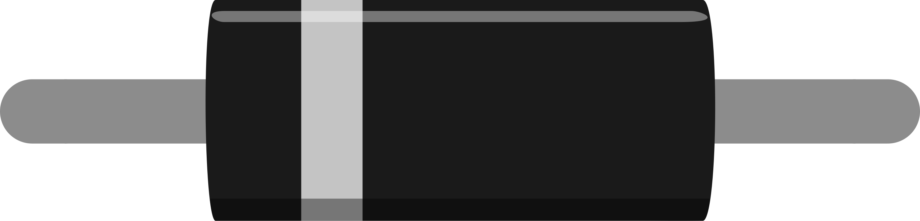
The cathode is typically marked with a silver or white band on the diode body.

Usage Instructions

How to Use the 1N5822 in a Circuit

  1. Identify the Anode and Cathode: The cathode is marked with a silver or white band. Connect the anode to the positive side of the circuit and the cathode to the negative side.
  2. Power Rectification: Use the 1N5822 in a bridge rectifier configuration for AC to DC conversion. Ensure the diode's reverse voltage rating (40V) exceeds the peak AC voltage.
  3. Voltage Clamping: Place the diode in parallel with the load to protect against voltage spikes. The low forward voltage drop ensures efficient clamping.
  4. Freewheeling Diode: In motor driver circuits, connect the 1N5822 across the motor terminals to prevent voltage spikes caused by inductive loads.

Important Considerations

  • Thermal Management: The 1N5822 can handle up to 3A of current, but proper heat dissipation is essential. Use a heatsink or ensure adequate ventilation if operating near the maximum current rating.
  • Reverse Voltage: Do not exceed the maximum reverse voltage of 40V to avoid damaging the diode.
  • Polarity: Always connect the diode with the correct polarity. Reversing the connections can lead to circuit failure.

Example: Using the 1N5822 with an Arduino UNO

The 1N5822 can be used for reverse polarity protection in an Arduino UNO circuit. Below is an example:

/*
 * Example: Reverse Polarity Protection with 1N5822
 * This circuit protects the Arduino UNO from damage if the power supply
 * is connected in reverse. The 1N5822 allows current to flow only in the
 * correct direction.
 */

void setup() {
  // No specific code is required for the diode itself.
  // This example assumes the diode is connected in series with the
  // Arduino's power input (VIN pin).
}

void loop() {
  // Your main code here
}

Circuit Connection:

  • Connect the anode of the 1N5822 to the positive terminal of the power supply.
  • Connect the cathode of the 1N5822 to the VIN pin of the Arduino UNO.
  • The diode will block current if the power supply is connected in reverse.

Troubleshooting and FAQs

Common Issues

  1. Excessive Heat Generation:

    • Cause: Operating the diode near or above its maximum current rating.
    • Solution: Use a heatsink or reduce the current load.
  2. Diode Not Conducting:

    • Cause: Incorrect polarity or damaged diode.
    • Solution: Verify the anode and cathode connections. Replace the diode if necessary.
  3. High Reverse Leakage Current:

    • Cause: Operating the diode at high temperatures or near its reverse voltage limit.
    • Solution: Ensure proper cooling and avoid exceeding the reverse voltage rating.

FAQs

Q1: Can I use the 1N5822 for high-frequency switching applications?
A1: Yes, the 1N5822's fast switching speed makes it suitable for high-frequency applications, such as DC-DC converters.

Q2: What happens if I exceed the reverse voltage rating?
A2: Exceeding the reverse voltage rating (40V) can cause the diode to break down and fail permanently.

Q3: Can I use the 1N5822 in a 12V automotive circuit?
A3: Yes, the 1N5822 is suitable for 12V systems, as its reverse voltage rating (40V) and current handling (3A) are adequate for most automotive applications.