How to Use ULN2803 Darlington Array: Examples, Pinouts, and Specs
Introduction
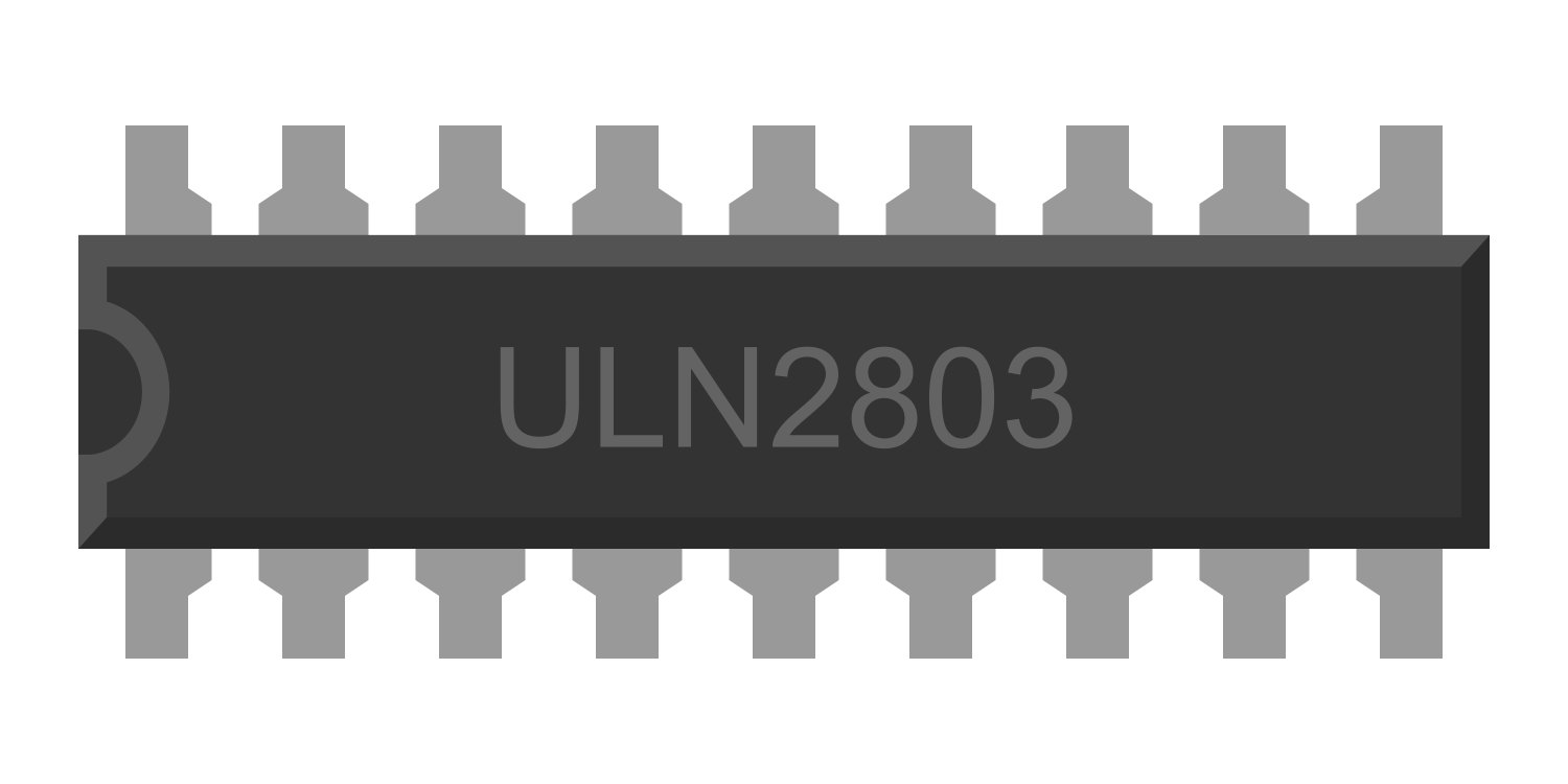
The ULN2803 Darlington Array is an integrated circuit that contains eight NPN Darlington pairs, each capable of driving high-current loads. It is designed to interface directly with TTL and CMOS logic signals. The common applications of the ULN2803 include driving relays, solenoids, LED displays, stepper motors, and other high-current or high-voltage loads in various electronic projects and commercial devices.
Explore Projects Built with ULN2803 Darlington Array
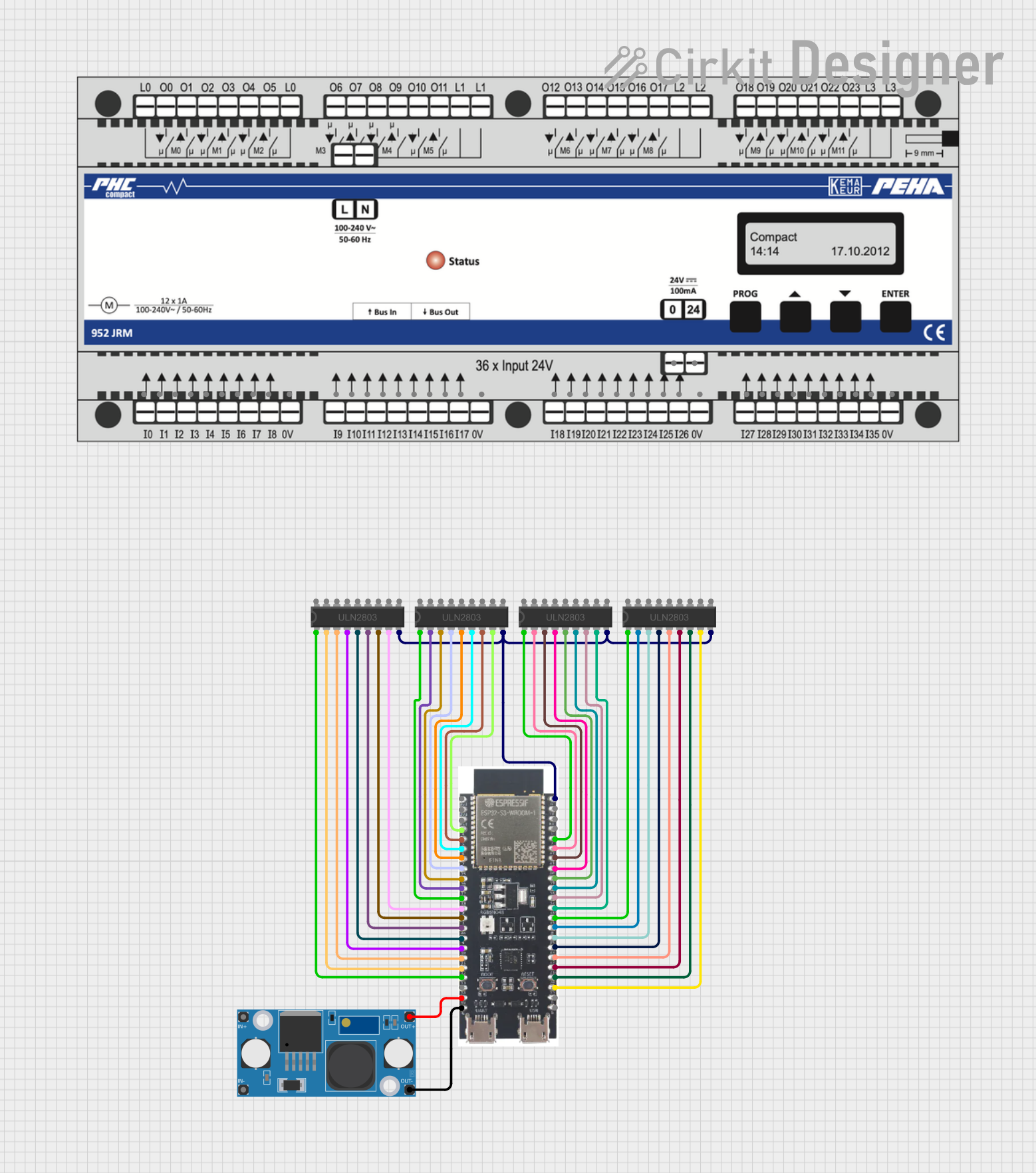
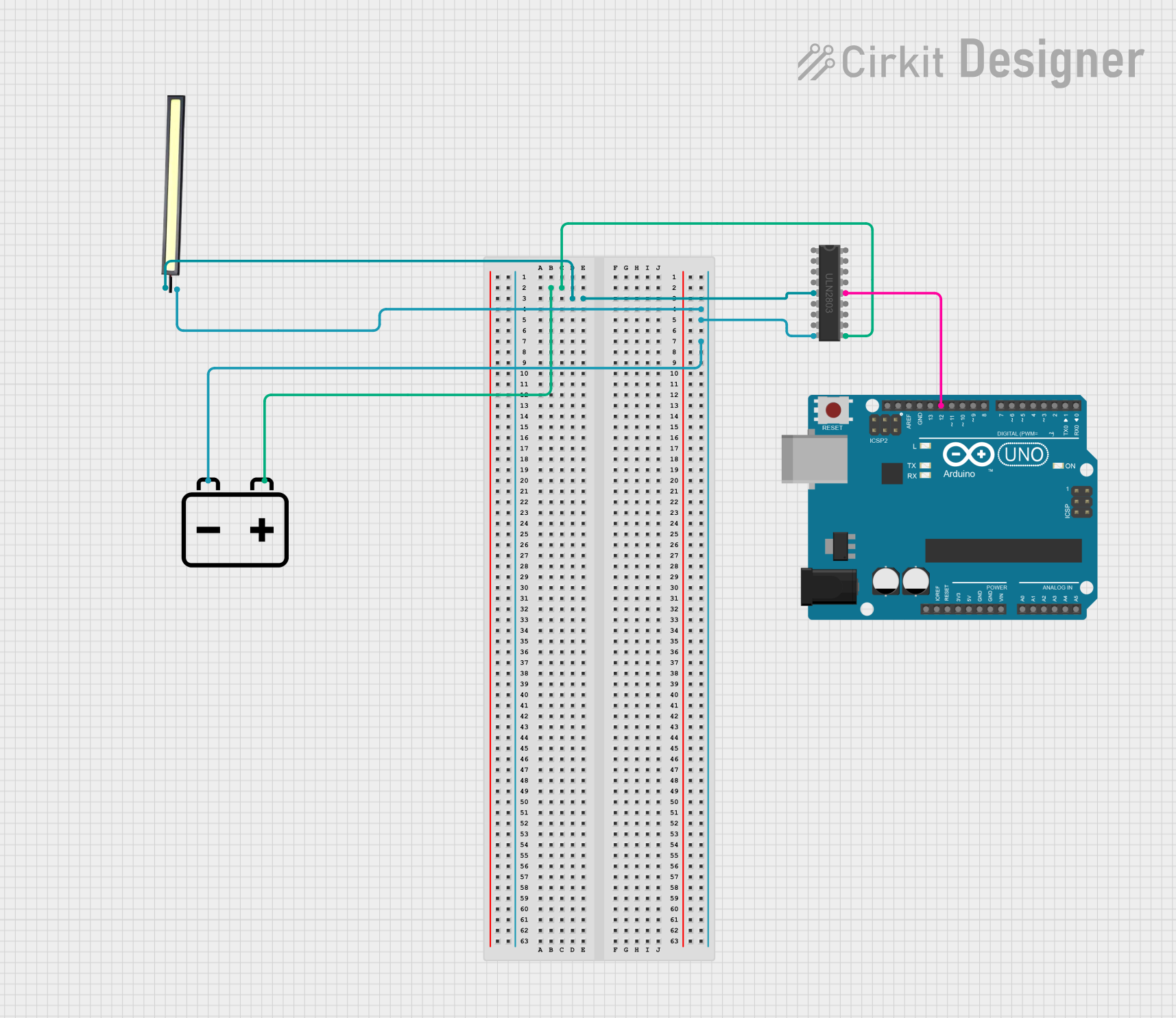
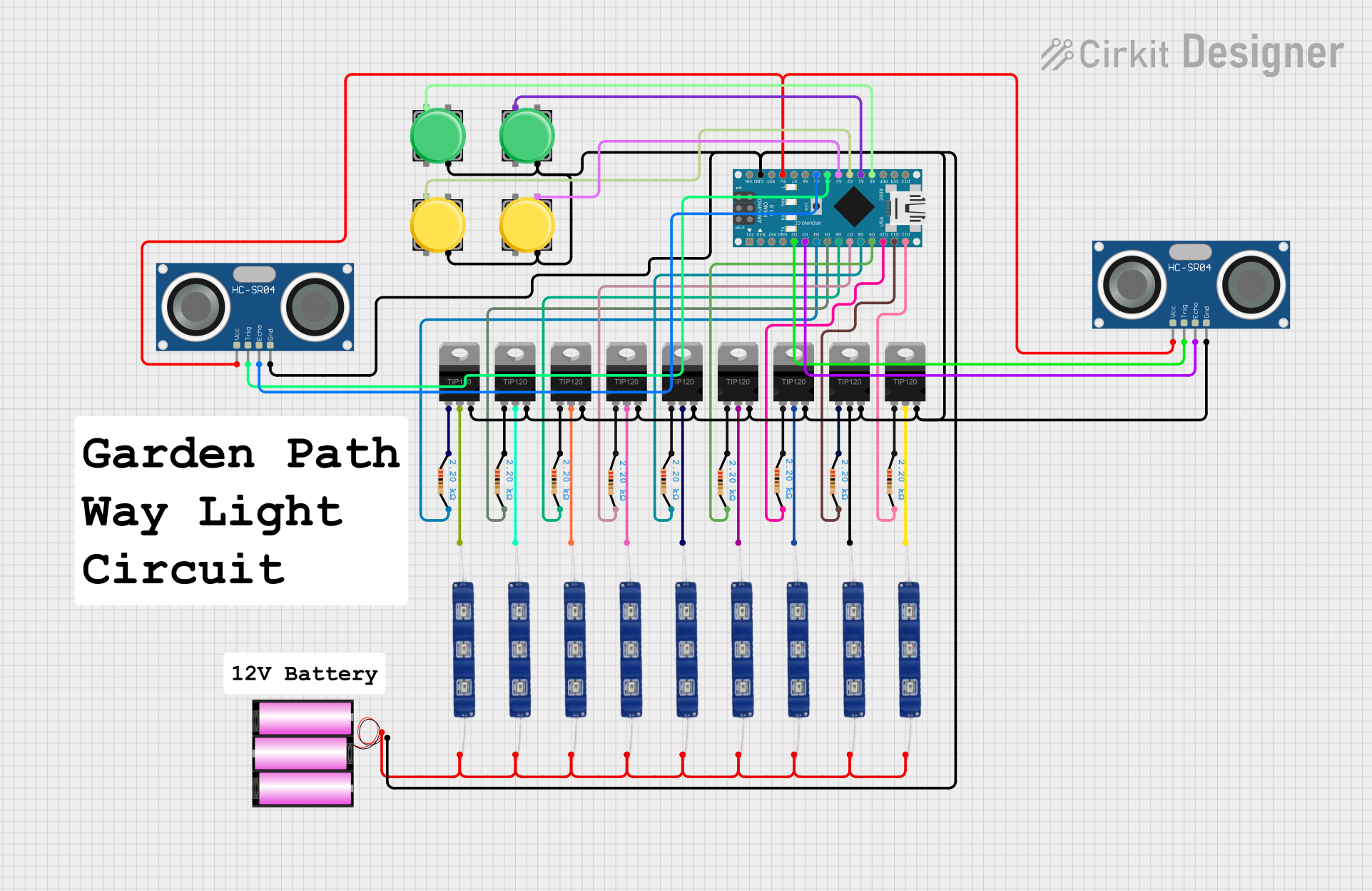
Explore Projects Built with ULN2803 Darlington Array
Technical Specifications
Key Technical Details
- Number of Channels: 8 Darlington pairs
- Input Voltage (V_IN): 2.4V to 5V (TTL/CMOS compatible)
- Output Voltage (V_OUT): 50V maximum
- Output Current (I_OUT): 500mA per channel, 2.5A peak for single channel
- Clamping Diodes: Built-in for inductive load suppression
- Mounting Type: Through-hole or Surface mount
Pin Configuration and Descriptions
| Pin Number | Pin Name | Description |
|---|---|---|
| 1-8 | Input 1-8 | Logic inputs from the microcontroller or logic device |
| 9 | GND | Ground connection |
| 10-17 | Output 1-8 | Outputs to the load |
| 18 | COM | Common free-wheeling diodes connection |
Usage Instructions
Interfacing with a Circuit
To use the ULN2803 Darlington Array in a circuit:
- Connect the inputs (pins 1-8) to the logic outputs from a microcontroller or logic device.
- Connect the outputs (pins 10-17) to the loads you wish to drive.
- Connect pin 9 to the ground of the logic circuit.
- Connect pin 18 to the positive supply voltage if using the internal clamp diodes for inductive loads.
Important Considerations and Best Practices
- Ensure that the power supply can handle the current requirements of the loads.
- Use external diodes for heavy inductive loads to protect the ULN2803.
- Avoid exceeding the maximum voltage and current ratings to prevent damage.
- Provide adequate heat sinking if operating near the maximum current ratings.
Example Code for Arduino UNO
// Example code to drive a relay using ULN2803 connected to an Arduino UNO

const int relayPin = 2; // Connect to ULN2803 input pin 1

void setup() {
  pinMode(relayPin, OUTPUT); // Set the relay pin as an output
}

void loop() {
  digitalWrite(relayPin, HIGH); // Turn on the relay
  delay(1000);                  // Wait for 1 second
  digitalWrite(relayPin, LOW);  // Turn off the relay
  delay(1000);                  // Wait for 1 second
}
Troubleshooting and FAQs
Common Issues
- LEDs or loads not activating: Check the input signal voltage and connections.
- Overheating: Ensure proper current flow and heat sinking.
- Unexpected behavior with inductive loads: Verify the COM pin is connected if using internal diodes.
Solutions and Tips
- Check Connections: Verify that all connections are secure and correct.
- Input Voltage: Ensure the input voltage is within the specified range for logic high signals.
- Power Supply: Use a power supply that can handle the current draw of all connected loads.
FAQs
Q: Can I drive loads that require more than 500mA with the ULN2803? A: Yes, but you may need to parallel multiple outputs for a single load, ensuring you do not exceed the total package current rating.
Q: Do I always need to connect the COM pin? A: The COM pin is only necessary if you are using the built-in clamp diodes for inductive loads. For non-inductive loads, it is not required.
Q: Can the ULN2803 be used with PWM signals? A: Yes, the ULN2803 can be used with PWM signals to control the speed of motors or the brightness of LEDs, for example.
For further assistance or more complex issues, please refer to the manufacturer's datasheet or contact technical support.