
How to Use DS18B20 1-Wire Temperature Sensor: Examples, Pinouts, and Specs
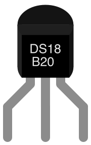
 Design with DS18B20 1-Wire Temperature Sensor in Cirkit Designer
Introduction
The DS18B20 is a digital temperature sensor manufactured by Maxim Integrated. It communicates using the 1-Wire protocol, which allows multiple sensors to share a single data line, simplifying wiring and reducing hardware requirements. The sensor provides accurate temperature readings in both Celsius and Fahrenheit, with a resolution of up to 12 bits. Its compact design and ease of use make it a popular choice for applications such as weather monitoring, industrial temperature control, and home automation systems.
Explore Projects Built with DS18B20 1-Wire Temperature Sensor
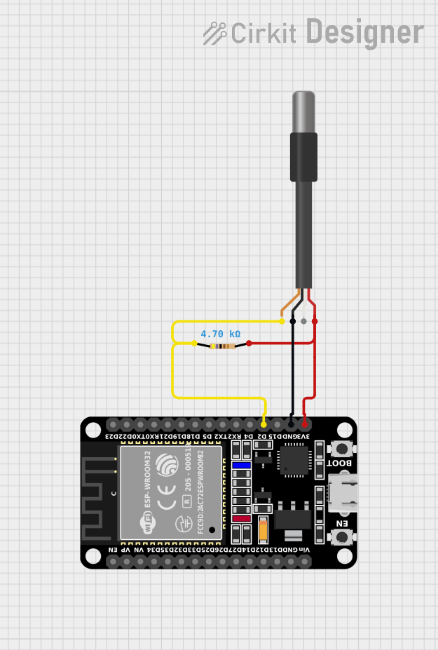 Open Project in Cirkit Designer
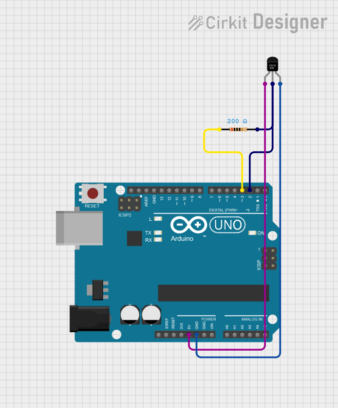 Open Project in Cirkit Designer
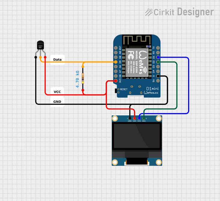 Open Project in Cirkit Designer
 Open Project in Cirkit Designer
Explore Projects Built with DS18B20 1-Wire Temperature Sensor
Open Project in Cirkit DesignerOpen Project in Cirkit DesignerOpen Project in Cirkit DesignerOpen Project in Cirkit DesignerCommon Applications
- Weather stations
- HVAC systems
- Home automation
- Industrial temperature monitoring
- Data logging systems
Technical Specifications
The DS18B20 is designed for precision and versatility. Below are its key technical details:
| Parameter | Value |
|---|---|
| Operating Voltage | 3.0V to 5.5V |
| Temperature Range | -55°C to +125°C |
| Accuracy | ±0.5°C (from -10°C to +85°C) |
| Resolution | Programmable: 9-bit to 12-bit |
| Communication Protocol | 1-Wire |
| Conversion Time | 93.75ms (12-bit resolution) |
| Unique 64-bit ROM Code | Yes (for device identification) |
| Power Modes | Parasitic power or external power |
| Package Options | TO-92, SOIC, and others |
Pin Configuration
The DS18B20 typically comes in a TO-92 package with three pins. Below is the pinout:
| Pin | Name | Description |
|---|---|---|
| 1 | GND | Ground pin. Connect to the ground of the circuit. |
| 2 | DQ | Data pin. Used for communication and data transfer via the 1-Wire protocol. |
| 3 | VDD | Power supply pin. Can be connected to 3.0V to 5.5V or left unconnected for parasitic power. |
Usage Instructions
Connecting the DS18B20 to a Circuit
- Power Supply: Connect the VDD pin to a 3.3V or 5V power source. Alternatively, leave it unconnected for parasitic power mode.
- Data Line: Connect the DQ pin to a microcontroller's GPIO pin. Use a 4.7kΩ pull-up resistor between the DQ pin and the power supply (VDD) to ensure proper communication.
- Ground: Connect the GND pin to the ground of the circuit.
Important Considerations
- Pull-Up Resistor: The 4.7kΩ pull-up resistor is essential for reliable communication on the 1-Wire bus.
- Parasitic Power Mode: If using parasitic power, ensure the DQ pin is pulled high during idle states to power the sensor.
- Multiple Sensors: Each DS18B20 has a unique 64-bit ROM code, allowing multiple sensors to be connected to the same data line. Use the ROM code to address individual sensors.
Example: Using DS18B20 with Arduino UNO
Below is an example of how to interface the DS18B20 with an Arduino UNO using the DallasTemperature and OneWire libraries.
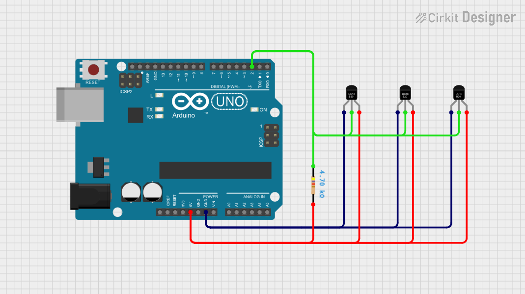
Circuit Diagram
- Connect the DQ pin to Arduino digital pin 2.
- Use a 4.7kΩ pull-up resistor between the DQ pin and the 5V pin.
- Connect the GND and VDD pins to the Arduino's GND and 5V pins, respectively.
Arduino Code
#include <OneWire.h>
#include <DallasTemperature.h>

// Data wire is connected to Arduino digital pin 2
#define ONE_WIRE_BUS 2

// Setup a oneWire instance to communicate with any OneWire devices
OneWire oneWire(ONE_WIRE_BUS);

// Pass the oneWire reference to DallasTemperature library
DallasTemperature sensors(&oneWire);

void setup() {
  Serial.begin(9600); // Start serial communication at 9600 baud
  sensors.begin();    // Initialize the DS18B20 sensor
}

void loop() {
  sensors.requestTemperatures(); // Send command to get temperature readings

  // Fetch and print the temperature in Celsius
  float temperatureC = sensors.getTempCByIndex(0);
  Serial.print("Temperature (C): ");
  Serial.println(temperatureC);

  // Fetch and print the temperature in Fahrenheit
  float temperatureF = sensors.getTempFByIndex(0);
  Serial.print("Temperature (F): ");
  Serial.println(temperatureF);

  delay(1000); // Wait 1 second before the next reading
}
Best Practices
- Use a decoupling capacitor (e.g., 0.1µF) between VDD and GND for improved stability.
- Avoid long wires for the 1-Wire bus to minimize signal degradation.
- If using multiple sensors, ensure each sensor's ROM code is correctly identified and addressed.
Troubleshooting and FAQs
Common Issues
No Temperature Reading:
- Ensure the pull-up resistor (4.7kΩ) is correctly connected between the DQ pin and VDD.
- Verify that the sensor is properly powered (check VDD and GND connections).
- Check the data pin connection to the microcontroller.
Incorrect Temperature Values:
- Ensure the sensor is operating within its specified temperature range (-55°C to +125°C).
- Verify that the resolution is correctly configured in the code.
Multiple Sensors Not Detected:
- Ensure each sensor is connected to the same data line.
- Use the unique 64-bit ROM code to address individual sensors.
FAQs
Q1: Can I use the DS18B20 with a 3.3V power supply?
Yes, the DS18B20 operates within a voltage range of 3.0V to 5.5V.
Q2: How many DS18B20 sensors can I connect to a single data line?
Theoretically, you can connect up to 100 sensors on a single 1-Wire bus, but this depends on factors like wire length and power supply.
Q3: What is the purpose of the pull-up resistor?
The pull-up resistor ensures the data line remains in a defined state (high) when no device is actively driving it.
Q4: Can I use the DS18B20 in outdoor applications?
Yes, but ensure the sensor is properly sealed or housed to protect it from moisture and extreme environmental conditions.
Q5: What is parasitic power mode?
In parasitic power mode, the sensor draws power from the data line (DQ) instead of the VDD pin. This reduces wiring but may limit performance in some cases.