How to Use AD9833: Examples, Pinouts, and Specs
Introduction
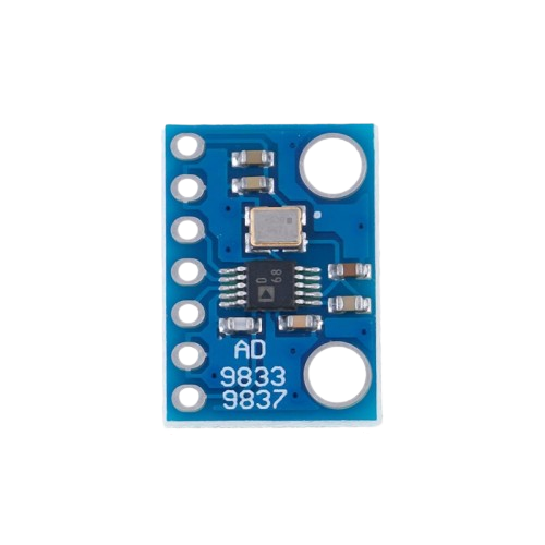
The AD9833 is a low-power, programmable waveform generator capable of producing sine, triangle, and square waves. This integrated circuit (IC) is controlled via a serial peripheral interface (SPI), allowing for the precise generation of waveforms for use in a variety of applications such as signal generation, local oscillators in communication systems, and function generators for testing and research.
Explore Projects Built with AD9833

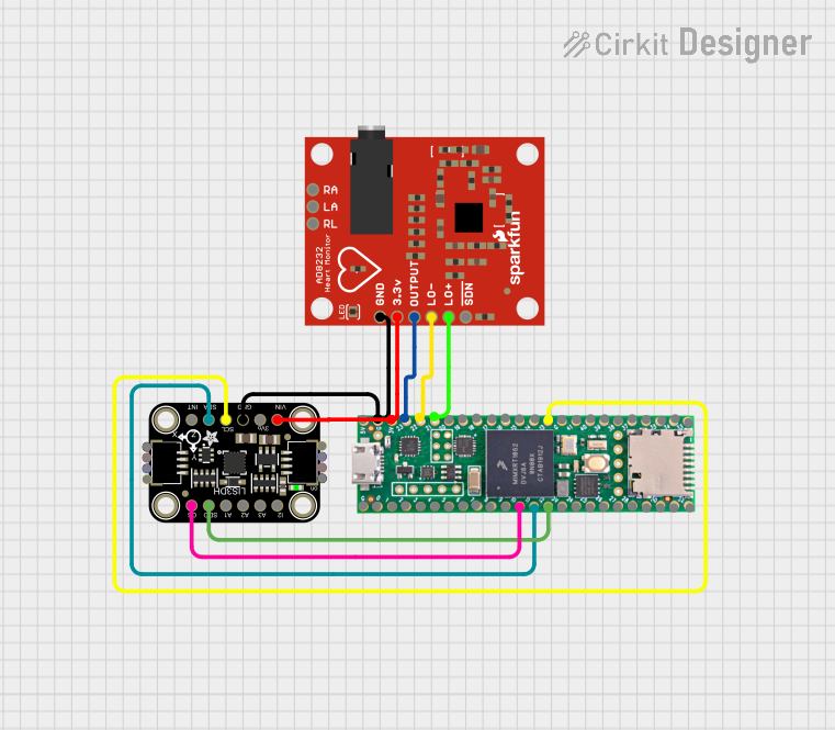
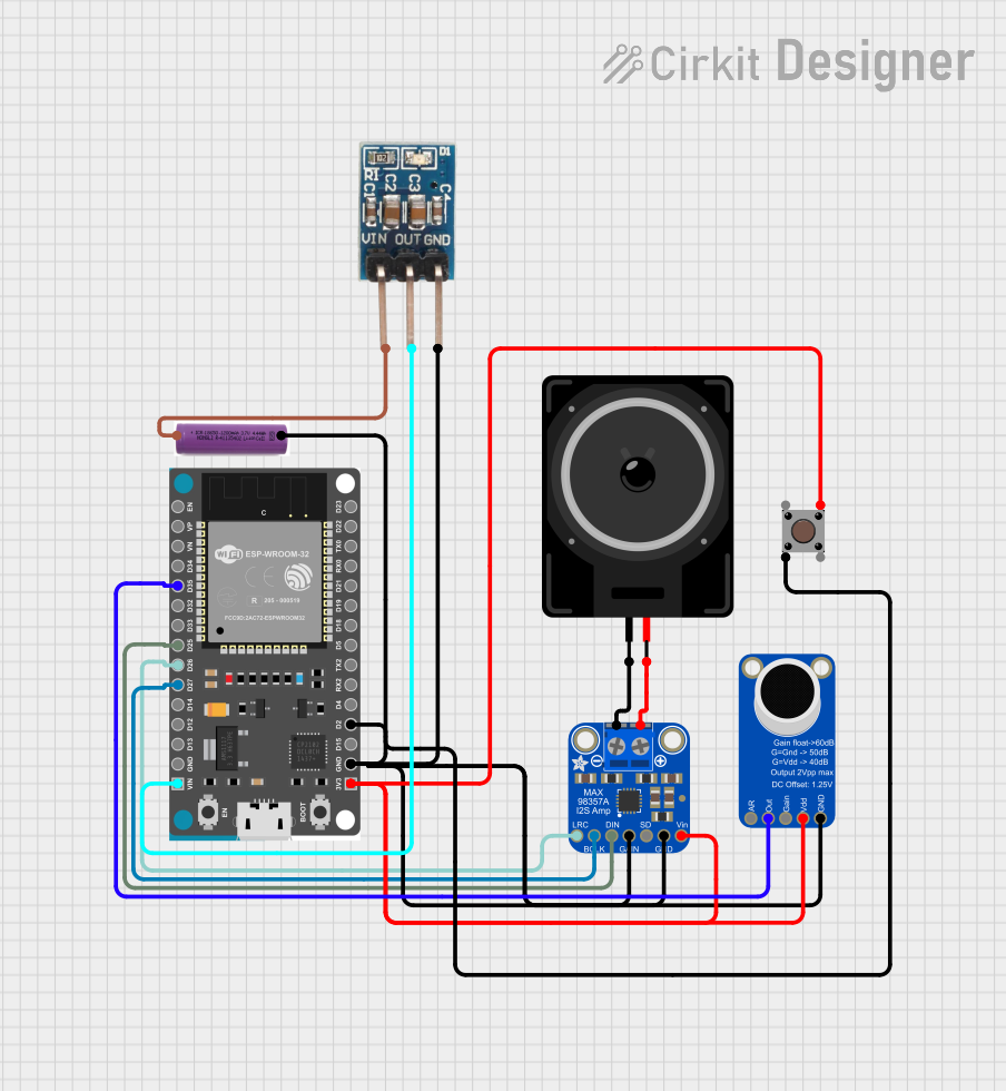
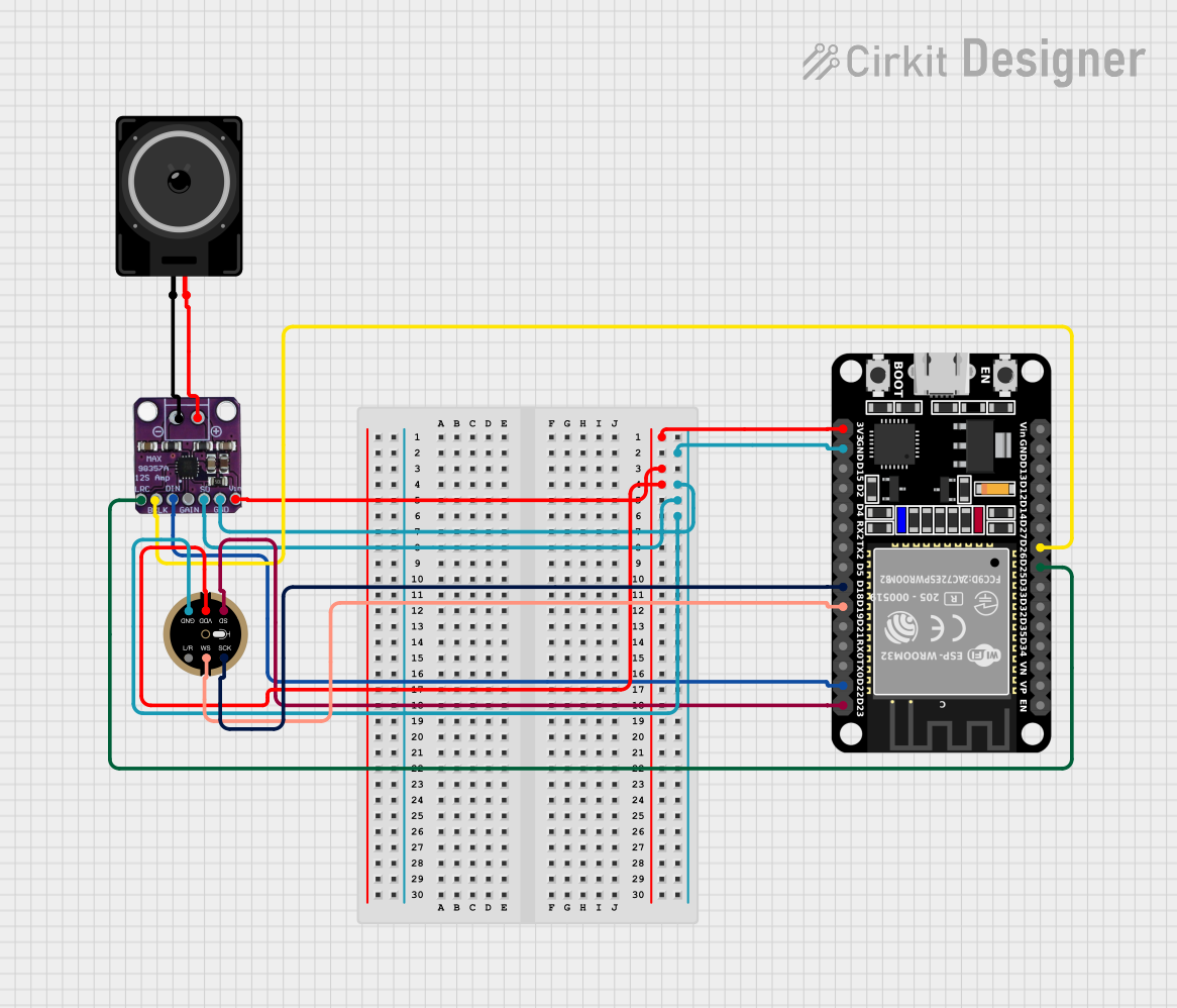
Explore Projects Built with AD9833
Common Applications and Use Cases
- Signal generation for bench testing
- Local oscillators in communication systems
- Function generators for educational purposes
- Prototyping and hobbyist projects, often interfaced with microcontrollers like Arduino
Technical Specifications
Key Technical Details
- Power Supply: 2.3V to 5.5V
- Frequency Range: 0.1 Hz to 12.5 MHz
- Resolution: 28-bit frequency resolution
- Output Waveforms: Sine, Triangle, Square
- Interface: 3-wire SPI
- Operating Temperature: -40°C to +105°C
Pin Configuration and Descriptions
| Pin Number | Name | Description |
|---|---|---|
| 1 | VDD | Positive power supply (2.3V to 5.5V) |
| 2 | GND | Ground reference for the power supply |
| 3 | SCLK | Serial clock input for SPI interface |
| 4 | SDATA | Serial data input for SPI interface |
| 5 | FSYNC | Frame synchronization signal for SPI interface |
| 6 | MCLK | Master clock input (up to 25 MHz) |
| 7 | COMP | Comparator output for square wave generation |
| 8 | VOUT | Analog output for sine or triangle wave |
Usage Instructions
How to Use the AD9833 in a Circuit
- Power Supply: Connect VDD to a 2.3V to 5.5V power source and GND to the system ground.
- Master Clock: Apply a stable clock signal to the MCLK pin. The frequency of this clock determines the output frequency range.
- SPI Interface: Connect SCLK, SDATA, and FSYNC to the corresponding SPI pins of the microcontroller.
- Output: Connect VOUT to the input of the next stage in your circuit. Use COMP for square wave output.
Important Considerations and Best Practices
- Ensure that the power supply is within the specified range and is stable.
- Use a decoupling capacitor close to the VDD pin to filter out noise.
- The MCLK should be a stable and accurate clock source as it directly affects the output waveform's accuracy.
- Keep the SPI signal lines as short as possible to minimize noise and ensure reliable communication.
- When interfacing with a microcontroller, ensure that the logic levels match the AD9833's requirements.
Example Code for Arduino UNO
#include <SPI.h>

// Define the SPI pins for Arduino UNO
const int FSYNC = 10; // Frame synchronization pin
const int SCLK = 13;  // Serial clock pin
const int SDATA = 11; // Serial data pin

void setup() {
  // Set the SPI pins to output
  pinMode(FSYNC, OUTPUT);
  digitalWrite(FSYNC, HIGH); // Set FSYNC high to start with
  SPI.begin();               // Initialize SPI interface
  SPI.setClockDivider(SPI_CLOCK_DIV16); // Set SPI clock speed
  // Initialize the AD9833 with a frequency of 1kHz
  initAD9833(1000);
}

void loop() {
  // The main loop can be used to update the frequency or waveform as needed
}

void initAD9833(unsigned long frequency) {
  // Calculate the frequency register value
  unsigned long freqReg = (frequency * pow(2, 28)) / 25000000UL;
  // Split the register value into two parts
  unsigned int MSB = (unsigned int)((freqReg & 0xFFFC000) >> 14);
  unsigned int LSB = (unsigned int)(freqReg & 0x3FFF);
  // Set control bits for the frequency register
  MSB |= 0x4000;
  LSB |= 0x4000;

  // Start the SPI transaction
  digitalWrite(FSYNC, LOW);
  SPI.transfer16(0x2100); // Reset the AD9833
  SPI.transfer16(LSB);    // Set lower 14 bits of frequency
  SPI.transfer16(MSB);    // Set upper 14 bits of frequency
  SPI.transfer16(0xC000); // Phase register
  SPI.transfer16(0x2000); // Exit reset
  digitalWrite(FSYNC, HIGH);
}
Troubleshooting and FAQs
Common Issues Users Might Face
- No Output Signal: Ensure that the power supply is connected correctly and within the specified range. Check the MCLK signal and the SPI connections.
- Incorrect Output Frequency: Verify the master clock frequency and the frequency calculation in the code. Ensure that the SPI communication is successful.
- Unstable Output Waveform: Check for noise in the power supply and the MCLK signal. Use a decoupling capacitor and keep signal lines short.
Solutions and Tips for Troubleshooting
- Always double-check connections and solder joints for any loose connections or shorts.
- Use an oscilloscope to verify the MCLK and SPI signals are as expected.
- If interfacing with a 5V microcontroller, ensure that the logic level for SDATA, SCLK, and FSYNC is compatible with the AD9833.
FAQs
Q: Can the AD9833 generate other waveforms besides sine, triangle, and square? A: The AD9833 is designed to generate sine, triangle, and square waves. For other waveforms, consider using a digital-to-analog converter (DAC) with a microcontroller.
Q: How can I change the waveform type? A: The waveform type can be changed by sending the appropriate control bits via the SPI interface. Refer to the AD9833 datasheet for the specific bits to set for each waveform type.
Q: What is the maximum frequency the AD9833 can generate? A: The AD9833 can generate frequencies up to 12.5 MHz, but this is dependent on the MCLK frequency provided.
Q: Is it possible to synchronize multiple AD9833 devices? A: Yes, multiple AD9833 devices can be synchronized by sharing the same MCLK signal and carefully managing the FSYNC signals for each device.