How to Use TCS3200: Examples, Pinouts, and Specs
Introduction
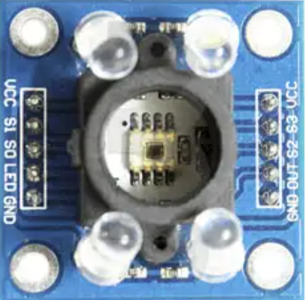
The TCS3200, manufactured by Texas Advanced Optoelectronic Solutions (part ID: GY-31), is a versatile color sensor capable of detecting and measuring the intensity of red, green, and blue light. It utilizes an array of photodiodes and an integrated current-to-frequency converter to output a frequency signal proportional to the intensity of the detected light. This makes it ideal for applications requiring color recognition or light intensity measurement.
Explore Projects Built with TCS3200
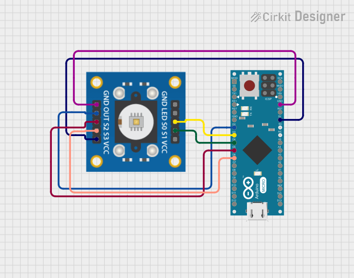
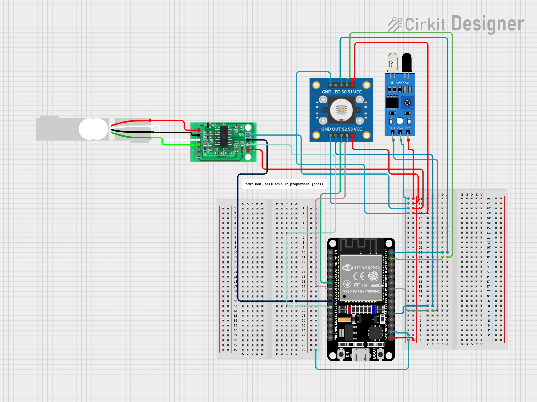

Explore Projects Built with TCS3200
Common Applications
- Color detection in robotics
- Sorting systems in industrial automation
- Ambient light sensing
- Color calibration in printing and display systems
- Educational projects and prototyping with microcontrollers (e.g., Arduino)
Technical Specifications
Key Technical Details
| Parameter | Value |
|---|---|
| Supply Voltage | 2.7V to 5.5V |
| Operating Current | 2mA (typical) |
| Output Frequency Range | 2Hz to 500kHz |
| Light Intensity Detection | Red, Green, Blue, and Clear (no filter) |
| Output Type | Square wave (frequency proportional to light intensity) |
| Operating Temperature | -40°C to +85°C |
| Dimensions | 28mm x 28mm (GY-31 breakout board) |
Pin Configuration and Descriptions
The TCS3200 is typically used on the GY-31 breakout board, which has the following pin layout:
| Pin Name | Pin Type | Description |
|---|---|---|
| VCC | Power Input | Connect to a 2.7V–5.5V power supply. |
| GND | Ground | Connect to the ground of the circuit. |
| OUT | Output Signal | Outputs a square wave with a frequency proportional to the detected light intensity. |
| S0 | Input Control | Used to set the output frequency scaling (see table below). |
| S1 | Input Control | Used to set the output frequency scaling (see table below). |
| S2 | Input Control | Used to select the photodiode filter (red, green, blue, or clear). |
| S3 | Input Control | Used to select the photodiode filter (red, green, blue, or clear). |
| OE | Input Control | Output enable pin (active low). Pull low to enable the output signal. |
Frequency Scaling Control (S0 and S1)
| S0 | S1 | Output Frequency Scaling |
|---|---|---|
| L | L | Power down mode |
| L | H | 2% |
| H | L | 20% |
| H | H | 100% |
Photodiode Filter Selection (S2 and S3)
| S2 | S3 | Selected Photodiode Filter |
|---|---|---|
| L | L | Red |
| L | H | Blue |
| H | L | Clear (no filter) |
| H | H | Green |
Usage Instructions
How to Use the TCS3200 in a Circuit
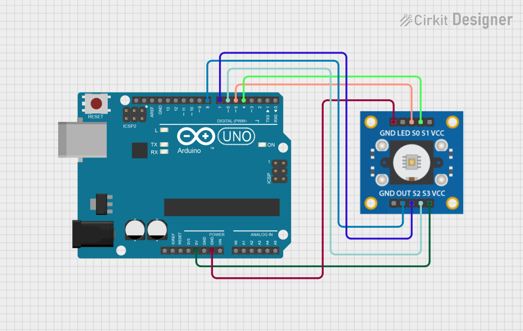
- Power Supply: Connect the VCC pin to a 3.3V or 5V power source and the GND pin to the ground.
- Output Signal: Connect the OUT pin to a microcontroller's digital input pin to read the frequency output.
- Control Pins:
- Use S0 and S1 to set the desired frequency scaling.
- Use S2 and S3 to select the desired photodiode filter (red, green, blue, or clear).
- Pull the OE pin low to enable the output signal.
- Microcontroller Interface: Use a microcontroller (e.g., Arduino) to measure the frequency of the OUT pin and calculate the light intensity for each color.
Important Considerations
- Frequency Scaling: Use the appropriate scaling factor (S0 and S1) to ensure the output frequency is within the measurable range of your microcontroller.
- Ambient Light: Minimize ambient light interference for accurate color detection.
- Calibration: Calibrate the sensor for your specific application to improve accuracy.
- Pull-up Resistors: Use pull-up resistors on the control pins if they are not actively driven by the microcontroller.
Example Arduino Code
Below is an example of how to interface the TCS3200 with an Arduino UNO to detect color:
// Pin definitions
#define S0 4  // Connect to S0 pin of TCS3200
#define S1 5  // Connect to S1 pin of TCS3200
#define S2 6  // Connect to S2 pin of TCS3200
#define S3 7  // Connect to S3 pin of TCS3200
#define OUT 8 // Connect to OUT pin of TCS3200

void setup() {
  // Set control pins as outputs
  pinMode(S0, OUTPUT);
  pinMode(S1, OUTPUT);
  pinMode(S2, OUTPUT);
  pinMode(S3, OUTPUT);

  // Set output frequency scaling to 20%
  digitalWrite(S0, HIGH);
  digitalWrite(S1, LOW);

  // Initialize serial communication
  Serial.begin(9600);
}

void loop() {
  // Select red filter
  digitalWrite(S2, LOW);
  digitalWrite(S3, LOW);
  delay(100); // Allow time for the sensor to stabilize

  // Measure frequency for red light
  int redFrequency = pulseIn(OUT, LOW);
  Serial.print("Red Frequency: ");
  Serial.println(redFrequency);

  // Select green filter
  digitalWrite(S2, HIGH);
  digitalWrite(S3, HIGH);
  delay(100);

  // Measure frequency for green light
  int greenFrequency = pulseIn(OUT, LOW);
  Serial.print("Green Frequency: ");
  Serial.println(greenFrequency);

  // Select blue filter
  digitalWrite(S2, LOW);
  digitalWrite(S3, HIGH);
  delay(100);

  // Measure frequency for blue light
  int blueFrequency = pulseIn(OUT, LOW);
  Serial.print("Blue Frequency: ");
  Serial.println(blueFrequency);

  delay(500); // Wait before the next reading
}
Troubleshooting and FAQs
Common Issues and Solutions
No Output Signal:
- Ensure the OE pin is pulled low to enable the output.
- Verify that the VCC and GND connections are secure.
- Check the frequency scaling settings (S0 and S1).
Inaccurate Color Detection:
- Calibrate the sensor for your specific lighting conditions.
- Reduce ambient light interference by shielding the sensor.
Microcontroller Cannot Read Frequency:
- Ensure the output frequency is within the measurable range of the microcontroller.
- Use the appropriate frequency scaling (e.g., 20% or 2%).
Sensor Not Responding:
- Verify that the control pins (S0, S1, S2, S3) are correctly configured.
- Check for loose or incorrect wiring.
FAQs
Q: Can the TCS3200 detect colors in complete darkness?
A: No, the TCS3200 requires a light source to detect colors. Use an external LED for illumination if necessary.
Q: How do I improve the accuracy of color detection?
A: Perform calibration by measuring known color samples and adjusting your calculations accordingly.
Q: Can I use the TCS3200 with a 3.3V microcontroller?
A: Yes, the TCS3200 operates with a supply voltage as low as 2.7V, making it compatible with 3.3V systems.
This concludes the documentation for the TCS3200 color sensor.