
How to Use Arduino UNO R3: Examples, Pinouts, and Specs
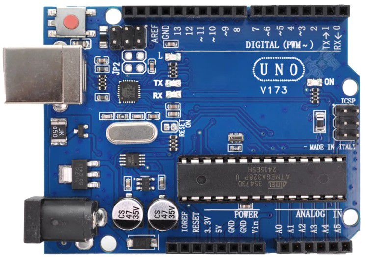
 Design with Arduino UNO R3 in Cirkit Designer
Introduction
The Arduino UNO R3 is a microcontroller board developed by Arduino, based on the ATmega328P microcontroller. It is one of the most popular and versatile development boards in the Arduino ecosystem, designed for beginners and professionals alike. The board features 14 digital input/output pins (6 of which can be used as PWM outputs), 6 analog inputs, a USB connection for programming, a power jack, and a reset button. Its simplicity and extensive community support make it ideal for prototyping, learning electronics, and building interactive projects.
Explore Projects Built with Arduino UNO R3
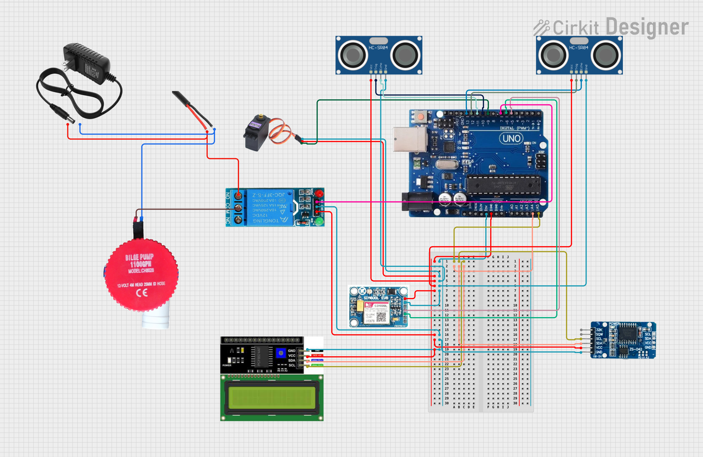 Open Project in Cirkit Designer
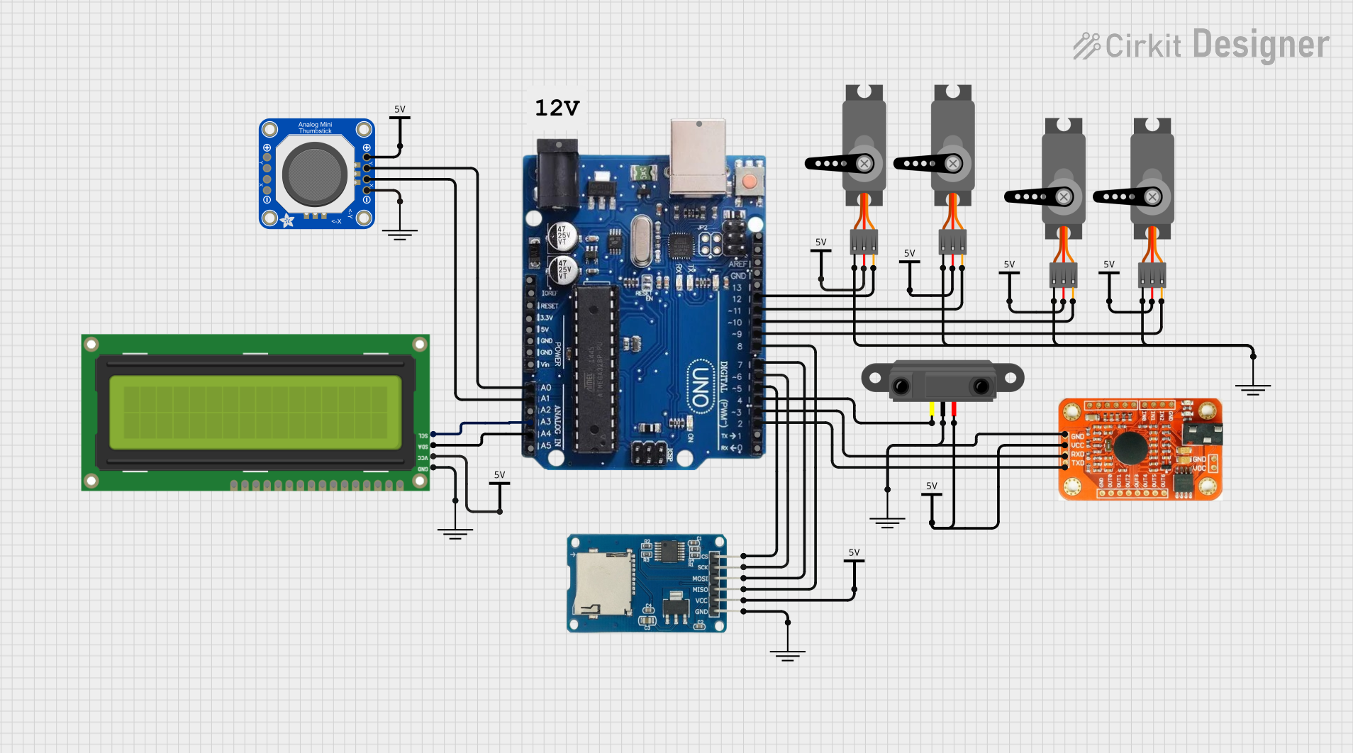 Open Project in Cirkit Designer
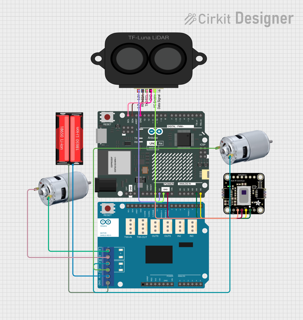 Open Project in Cirkit Designer
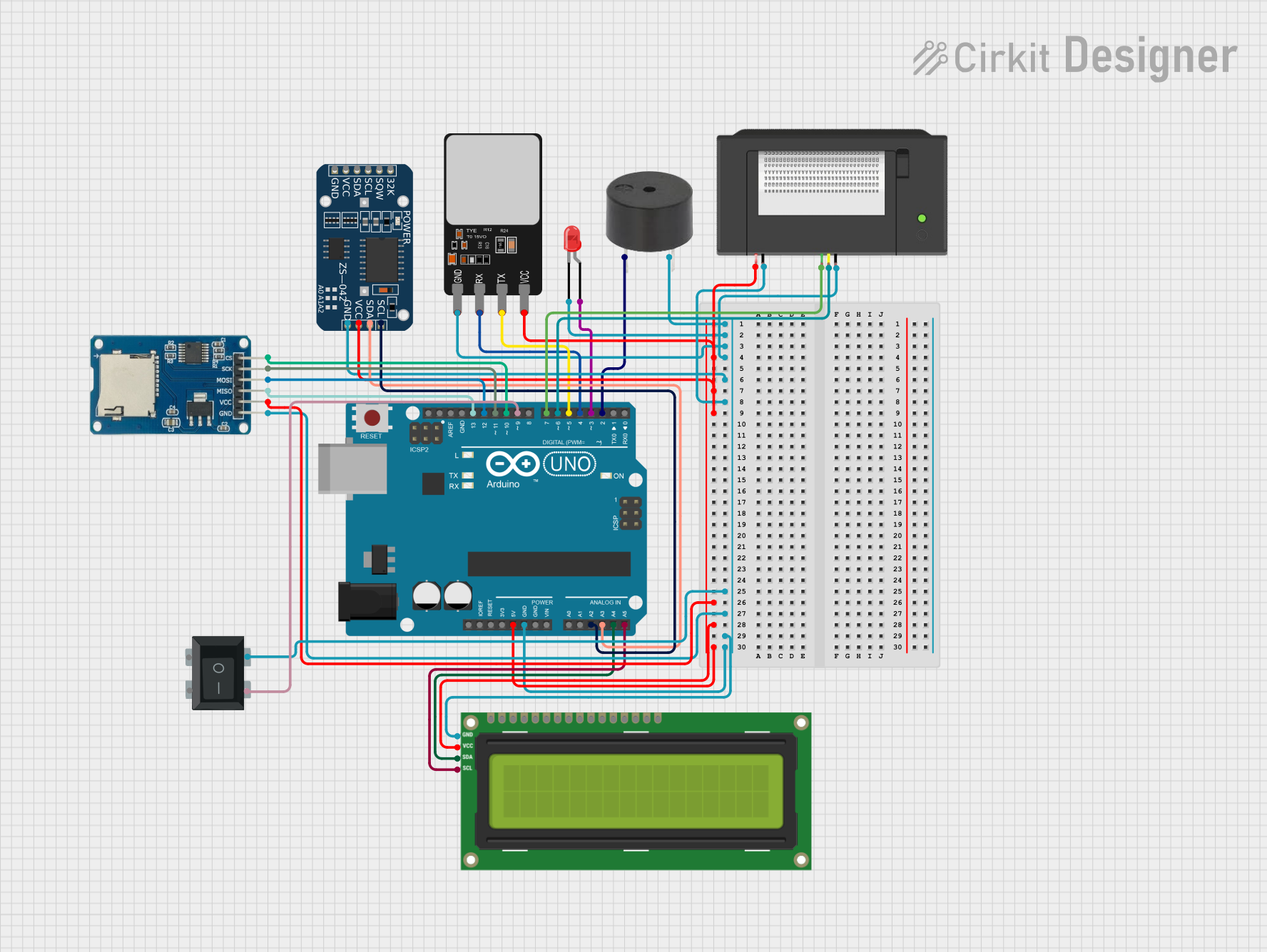 Open Project in Cirkit Designer
Explore Projects Built with Arduino UNO R3
Open Project in Cirkit DesignerOpen Project in Cirkit DesignerOpen Project in Cirkit DesignerOpen Project in Cirkit DesignerCommon Applications and Use Cases
- Prototyping and testing electronic circuits
- Building IoT (Internet of Things) devices
- Robotics and automation projects
- Interactive art installations
- Educational tools for learning programming and electronics
Technical Specifications
The Arduino UNO R3 is equipped with the following key features and specifications:
| Specification | Details |
|---|---|
| Microcontroller | ATmega328P |
| Operating Voltage | 5V |
| Input Voltage (recommended) | 7-12V |
| Input Voltage (limit) | 6-20V |
| Digital I/O Pins | 14 (6 PWM outputs) |
| Analog Input Pins | 6 |
| DC Current per I/O Pin | 20 mA |
| Flash Memory | 32 KB (0.5 KB used by bootloader) |
| SRAM | 2 KB |
| EEPROM | 1 KB |
| Clock Speed | 16 MHz |
| USB Connector | Type-B |
| Dimensions | 68.6 mm x 53.4 mm |
| Weight | 25 g |
Pin Configuration and Descriptions
The Arduino UNO R3 has a total of 28 pins, including digital, analog, power, and communication pins. Below is a detailed description of the pin configuration:
Digital Pins
| Pin Number | Function | Description |
|---|---|---|
| 0 (RX) | UART Receive | Used for serial communication (receives data). |
| 1 (TX) | UART Transmit | Used for serial communication (transmits data). |
| 2-13 | Digital I/O | General-purpose digital input/output pins. |
| 3, 5, 6, 9, 10, 11 | PWM Output | Can output PWM signals for motor control, LED dimming, etc. |
Analog Pins
| Pin Number | Function | Description |
|---|---|---|
| A0-A5 | Analog Input | Reads analog signals (0-5V) and converts them to a 10-bit digital value (0-1023). |
Power Pins
| Pin Name | Function | Description |
|---|---|---|
| VIN | Input Voltage | Input voltage to the board when using an external power source (7-12V). |
| 5V | Regulated 5V Output | Provides a regulated 5V output for powering external components. |
| 3.3V | Regulated 3.3V Output | Provides a regulated 3.3V output for low-voltage components. |
| GND | Ground | Common ground for the circuit. |
| RESET | Reset | Resets the microcontroller. |
Communication Pins
| Pin Name | Function | Description |
|---|---|---|
| SDA | I2C Data | Used for I2C communication. |
| SCL | I2C Clock | Used for I2C communication. |
| SPI (10, 11, 12, 13) | SPI Communication | Used for SPI communication with external devices. |
Usage Instructions
How to Use the Arduino UNO R3 in a Circuit
Powering the Board:
- Connect the board to your computer using a USB Type-B cable for programming and power.
- Alternatively, use an external power source (7-12V) via the VIN pin or the DC power jack.
Programming the Board:
- Install the Arduino IDE from the official Arduino website.
- Connect the board to your computer and select the correct board ("Arduino UNO") and port in the IDE.
- Write your code in the IDE and upload it to the board using the "Upload" button.
Connecting Components:
- Use the digital and analog pins to connect sensors, actuators, and other components.
- Ensure that the current and voltage requirements of your components are within the board's limits.
Using Shields:
- The Arduino UNO R3 supports a wide range of shields (e.g., motor shields, Wi-Fi shields).
- Stack the shield onto the board, ensuring proper alignment of the pins.
Important Considerations and Best Practices
- Avoid drawing more than 20 mA from any single I/O pin to prevent damage to the microcontroller.
- Use external pull-up or pull-down resistors for stable digital input signals.
- When using motors or high-power components, use external power supplies and proper isolation circuits.
- Always double-check your connections to avoid short circuits or incorrect wiring.
Example Code for Blinking an LED
The following example demonstrates how to blink an LED connected to pin 13 of the Arduino UNO R3:
// This program blinks an LED connected to pin 13 on the Arduino UNO R3.
// The LED will turn on for 1 second and off for 1 second in a loop.

void setup() {
  pinMode(13, OUTPUT); // Set pin 13 as an output pin
}

void loop() {
  digitalWrite(13, HIGH); // Turn the LED on
  delay(1000);            // Wait for 1 second
  digitalWrite(13, LOW);  // Turn the LED off
  delay(1000);            // Wait for 1 second
}
Troubleshooting and FAQs
Common Issues and Solutions
The board is not detected by the computer:
- Ensure the USB cable is properly connected and functional.
- Check if the correct port is selected in the Arduino IDE.
- Install or update the USB drivers for the Arduino UNO.
Code does not upload to the board:
- Verify that the correct board ("Arduino UNO") is selected in the Arduino IDE.
- Press the reset button on the board before uploading the code.
- Ensure no other program is using the COM port.
Components are not working as expected:
- Double-check the wiring and connections.
- Verify that the components are compatible with the Arduino UNO's voltage and current ratings.
- Use a multimeter to test for continuity and proper voltage levels.
FAQs
Q: Can I power the Arduino UNO R3 with a battery?
A: Yes, you can power the board using a 9V battery connected to the DC power jack or the VIN pin.
Q: What is the maximum current the board can supply?
A: The 5V pin can supply up to 500 mA when powered via USB, and up to 1A when powered via an external power source.
Q: Can I use the Arduino UNO R3 for wireless communication?
A: Yes, you can use shields or modules like the ESP8266 or Bluetooth modules for wireless communication.
Q: Is the Arduino UNO R3 compatible with other Arduino shields?
A: Yes, the Arduino UNO R3 is compatible with most Arduino shields designed for the standard UNO form factor.