How to Use 7'' display with HDMI: Examples, Pinouts, and Specs
7-Inch HDMI Display Documentation
1. Introduction
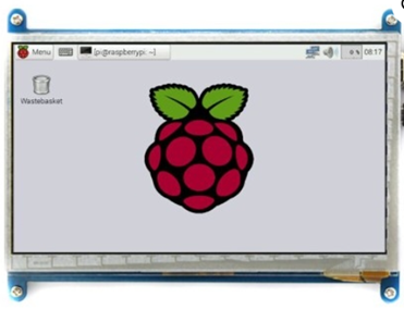
The 7-inch HDMI Display (Manufacturer Part ID: HDMI display) is a compact, high-definition screen designed for a wide range of applications. With its HDMI input, this display supports seamless video and audio transmission from compatible devices, making it ideal for projects requiring a clear and vibrant visual interface. Its small form factor and plug-and-play functionality make it a popular choice for hobbyists, developers, and professionals alike.
Common Applications:
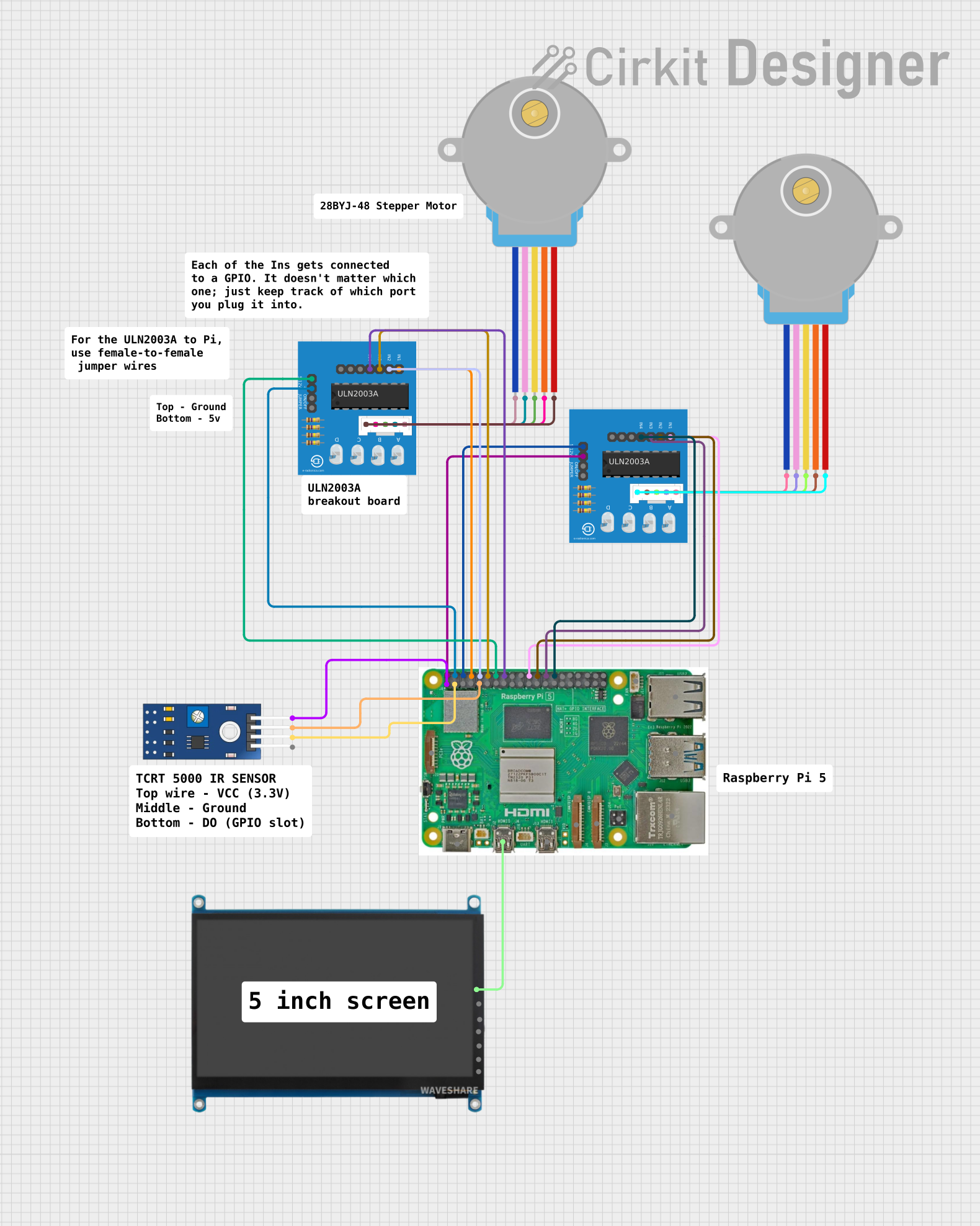
- Embedded Systems: Used with microcontrollers like Raspberry Pi, Arduino (with HDMI shields), and other development boards.
- Portable Monitors: Acts as a secondary or primary display for laptops, gaming consoles, or media players.
- DIY Projects: Perfect for custom projects such as smart mirrors, kiosks, or home automation interfaces.
- Prototyping: Ideal for testing and debugging visual outputs in hardware and software development.
2. Technical Specifications
The following table outlines the key technical details of the 7-inch HDMI Display:
| Parameter | Specification |
|---|---|
| Display Size | 7 inches |
| Resolution | 1024 x 600 pixels |
| Aspect Ratio | 16:9 |
| Input Interface | HDMI |
| Power Supply | 5V DC (via micro-USB or GPIO pins) |
| Current Consumption | ~500mA |
| Viewing Angle | 170° horizontal, 160° vertical |
| Touchscreen | Optional (capacitive or resistive, depending on the model) |
| Backlight | LED |
| Operating Temperature | -20°C to 70°C |
| Dimensions | 164.9mm x 100mm x 15mm |
| Weight | ~200g |
Pin Configuration (Power and Touchscreen Models)
| Pin | Name | Description |
|---|---|---|
| 1 | 5V | Power input (5V DC) |
| 2 | GND | Ground |
| 3 | SDA | I2C Data Line (for touchscreen models) |
| 4 | SCL | I2C Clock Line (for touchscreen models) |
| 5 | INT | Interrupt pin (used for touchscreen functionality) |
3. Usage Instructions
Connecting the Display
Power the Display:
- Use a 5V DC power source via the micro-USB port or GPIO pins.
- Ensure the power supply can provide at least 500mA to avoid flickering or instability.
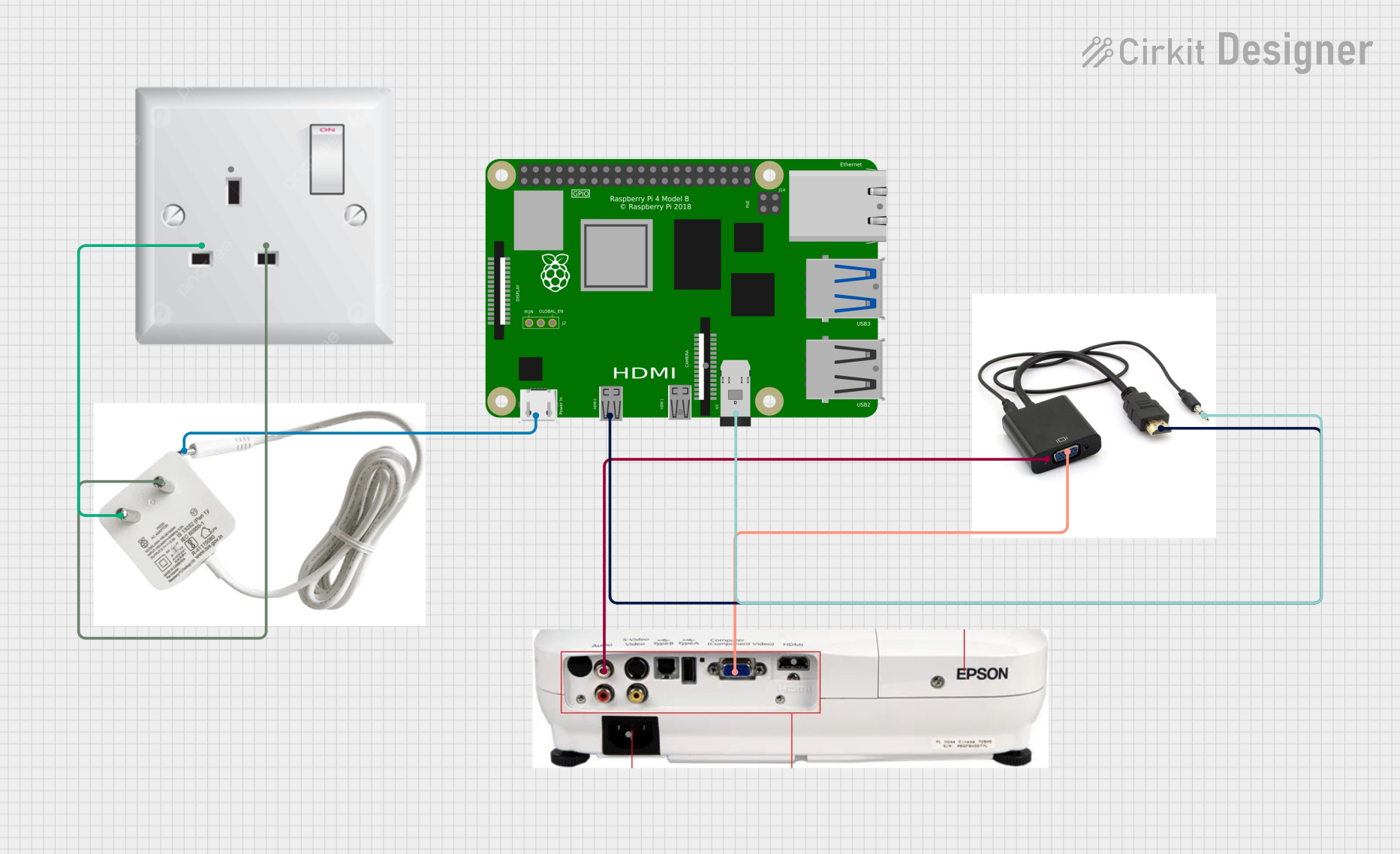
Connect HDMI Input:
- Plug an HDMI cable into the display's HDMI port and connect the other end to your device (e.g., Raspberry Pi, laptop, or gaming console).
Optional Touchscreen Setup:
- If using a touchscreen model, connect the I2C pins (SDA, SCL, INT) to your microcontroller or development board.
Adjust Display Settings:
- Use the device's display settings to configure resolution and orientation if needed.
Example: Using with an Arduino UNO (via HDMI Shield)
To use the 7-inch HDMI Display with an Arduino UNO, you will need an HDMI shield or adapter. Follow these steps:
- Attach the HDMI shield to the Arduino UNO.
- Connect the display's HDMI port to the shield using an HDMI cable.
- Power the display using a 5V micro-USB cable or GPIO pins.
- Upload your sketch to the Arduino UNO to output data to the display.
4. Sample Code for Arduino UNO
Below is an example of how to display text on the 7-inch HDMI Display using an Arduino UNO and an HDMI shield. This example assumes the use of a compatible graphics library (e.g., Adafruit GFX).
#include <Adafruit_GFX.h>  // Include the Adafruit GFX library
#include <Adafruit_HDMI.h> // Include the HDMI library for the shield

Adafruit_HDMI display; // Create an instance of the HDMI display

void setup() {
  // Initialize the display
  if (!display.begin()) {
    Serial.println("Display initialization failed!");
    while (1); // Halt if the display fails to initialize
  }

  // Set text properties
  display.setTextSize(2);       // Set text size
  display.setTextColor(WHITE); // Set text color
  display.setCursor(10, 10);    // Set cursor position

  // Display a message
  display.println("Hello, HDMI Display!");
}

void loop() {
  // No additional code needed for this example
}
Note: Ensure you have installed the required libraries (Adafruit GFX and HDMI) in your Arduino IDE. The HDMI shield must be compatible with the Arduino UNO.
5. Troubleshooting and FAQs
Common Issues and Solutions
| Issue | Possible Cause | Solution |
|---|---|---|
| No display output | HDMI cable not connected properly | Check HDMI connections and ensure the source device is powered on. |
| Flickering or unstable display | Insufficient power supply | Use a 5V power source capable of providing at least 500mA. |
| Touchscreen not responding | I2C pins not connected or misconfigured | Verify SDA, SCL, and INT connections. Check I2C address in your code. |
| Incorrect resolution or scaling | Device output resolution mismatch | Adjust the resolution settings on the source device to match 1024x600. |
| Display not turning on | Power supply issue | Ensure the micro-USB cable or GPIO pins are providing 5V. |
Frequently Asked Questions (FAQs)
Can I use this display with a Raspberry Pi?
- Yes, the display is fully compatible with Raspberry Pi models that support HDMI output.
Does the display support audio?
- Yes, the HDMI interface supports audio transmission, but the display does not have built-in speakers. You can use external speakers connected to your source device.
Can I power the display using GPIO pins?
- Yes, you can power the display using the 5V and GND GPIO pins, but ensure the power source is stable.
Is the touchscreen feature mandatory?
- No, the touchscreen is optional and only available on specific models.
What is the maximum resolution supported?
- The display supports a maximum resolution of 1024x600 pixels.
6. Additional Resources
For further assistance, contact the manufacturer or refer to the product datasheet.
Explore Projects Built with 7'' display with HDMI


Explore Projects Built with 7'' display with HDMI