
How to Use LM358 Op-Amp: Examples, Pinouts, and Specs
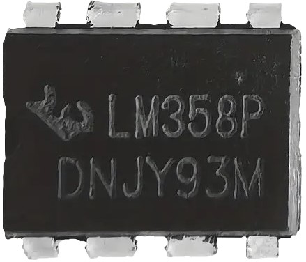
 Design with LM358 Op-Amp in Cirkit Designer
Introduction
The LM358B, manufactured by Texas Instruments, is a dual operational amplifier (op-amp) designed for a wide range of applications. It can operate on a single power supply or dual power supplies, making it versatile for various circuit designs. The LM358B is known for its high gain, low noise, and low power consumption, making it ideal for signal conditioning, filtering, and amplification tasks.
Explore Projects Built with LM358 Op-Amp
 Open Project in Cirkit Designer
 Open Project in Cirkit Designer
 Open Project in Cirkit Designer
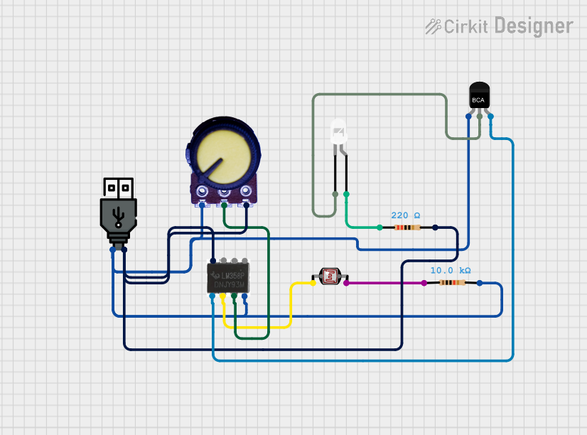 Open Project in Cirkit Designer
Explore Projects Built with LM358 Op-Amp
Open Project in Cirkit DesignerOpen Project in Cirkit DesignerOpen Project in Cirkit DesignerOpen Project in Cirkit DesignerCommon Applications
- Signal amplification in audio and sensor circuits
- Active filters and integrators
- Voltage followers (buffer circuits)
- Comparator circuits
- Analog signal processing in embedded systems
Technical Specifications
Key Technical Details
| Parameter | Value |
|---|---|
| Manufacturer | Texas Instruments |
| Part Number | LM358B |
| Number of Channels | 2 (Dual Op-Amp) |
| Supply Voltage Range | Single Supply: 3V to 32V |
| Dual Supply: ±1.5V to ±16V | |
| Input Offset Voltage | 2 mV (typical) |
| Input Bias Current | 20 nA (typical) |
| Gain Bandwidth Product | 1 MHz |
| Slew Rate | 0.3 V/µs |
| Output Voltage Swing | 0V to (V+ - 1.5V) |
| Operating Temperature Range | -40°C to +125°C |
| Package Options | SOIC, PDIP, TSSOP, and others |
Pin Configuration and Descriptions
The LM358B is available in an 8-pin package. Below is the pinout and description for the 8-pin PDIP/SOIC package:
| Pin Number | Pin Name | Description |
|---|---|---|
| 1 | OUT1 | Output of Op-Amp 1 |
| 2 | IN1- | Inverting Input of Op-Amp 1 |
| 3 | IN1+ | Non-Inverting Input of Op-Amp 1 |
| 4 | V- (GND) | Negative Power Supply or Ground |
| 5 | IN2+ | Non-Inverting Input of Op-Amp 2 |
| 6 | IN2- | Inverting Input of Op-Amp 2 |
| 7 | OUT2 | Output of Op-Amp 2 |
| 8 | V+ | Positive Power Supply |
Usage Instructions
How to Use the LM358B in a Circuit
- Power Supply: Connect the LM358B to a single power supply (e.g., 5V or 12V) or a dual power supply (e.g., ±12V). Ensure the supply voltage is within the specified range (3V to 32V for single supply or ±1.5V to ±16V for dual supply).
- Input Connections:
- For amplification, connect the input signal to the non-inverting input (INx+) or the inverting input (INx-), depending on the desired configuration (non-inverting or inverting amplifier).
- Use appropriate resistors to set the gain of the amplifier.
- Output Connections: The output (OUTx) can drive loads directly, but ensure the load impedance is high enough to avoid excessive current draw.
- Bypass Capacitor: Place a decoupling capacitor (e.g., 0.1 µF) close to the power supply pins to reduce noise and improve stability.
Example: Non-Inverting Amplifier Circuit
Below is an example of using the LM358B as a non-inverting amplifier with an Arduino UNO:
Circuit Diagram
- Connect the LM358B as follows:
- V+ to 5V (Arduino 5V pin)
- V- to GND (Arduino GND pin)
- IN1+ to the input signal (e.g., a sensor output)
- IN1- connected to a voltage divider for gain setting
- OUT1 to an analog input pin on the Arduino (e.g., A0)
Arduino Code
// LM358B Non-Inverting Amplifier Example
// Reads the amplified signal from the LM358B and displays it via Serial Monitor

const int analogPin = A0; // Analog pin connected to LM358B OUT1

void setup() {
  Serial.begin(9600); // Initialize serial communication at 9600 baud
}

void loop() {
  int sensorValue = analogRead(analogPin); // Read the amplified signal
  float voltage = sensorValue * (5.0 / 1023.0); // Convert ADC value to voltage
  Serial.print("Amplified Voltage: ");
  Serial.print(voltage);
  Serial.println(" V");
  delay(500); // Wait for 500 ms before the next reading
}
Important Considerations and Best Practices
- Input Voltage Range: Ensure the input voltage stays within the common-mode input range of the LM358B to avoid distortion or incorrect operation.
- Output Swing: The output cannot reach the exact supply voltage levels. For single-supply operation, the output typically swings from 0V to (V+ - 1.5V).
- Thermal Management: Operate the LM358B within its specified temperature range (-40°C to +125°C) to ensure reliable performance.
- Stability: Use proper bypass capacitors and avoid excessive capacitive loads on the output to maintain stability.
Troubleshooting and FAQs
Common Issues and Solutions
No Output Signal:
- Verify the power supply connections (V+ and V-).
- Check the input signal and ensure it is within the common-mode range.
- Confirm that the gain-setting resistors are correctly connected.
Distorted Output:
- Ensure the input signal amplitude does not exceed the input voltage range.
- Check if the output load impedance is too low, causing excessive current draw.
Oscillations or Noise:
- Add a decoupling capacitor (e.g., 0.1 µF) near the power supply pins.
- Avoid long, unshielded wires for input and output connections.
Output Voltage Not Reaching Expected Levels:
- Remember that the output swing is limited to 0V to (V+ - 1.5V) in single-supply mode.
- Use a dual power supply if a full bipolar output swing is required.
FAQs
Q1: Can the LM358B be used for audio amplification?
A1: Yes, the LM358B can be used for basic audio amplification, but its bandwidth and slew rate may limit performance in high-fidelity audio applications.
Q2: What is the difference between LM358 and LM358B?
A2: The LM358B is an improved version of the LM358 with better specifications, such as lower input offset voltage and improved performance.
Q3: Can I use the LM358B with a 3.3V power supply?
A3: Yes, the LM358B can operate with a single supply as low as 3V, making it suitable for 3.3V systems.
Q4: Is the LM358B suitable for battery-powered applications?
A4: Yes, the LM358B has low power consumption, making it ideal for battery-powered devices.