How to Use H11AA1: Examples, Pinouts, and Specs
Introduction
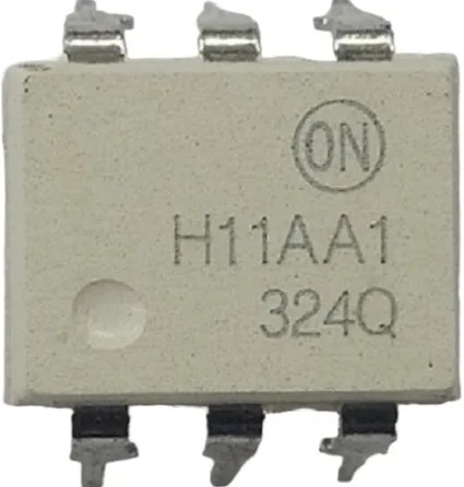
The H11AA1 is an optocoupler designed to provide electrical isolation between its input and output. It consists of an internal light-emitting diode (LED) and a phototransistor, enabling signal transmission without a direct electrical connection. This isolation is crucial in protecting sensitive components from high voltages, noise, or ground loops in electronic circuits.
Explore Projects Built with H11AA1
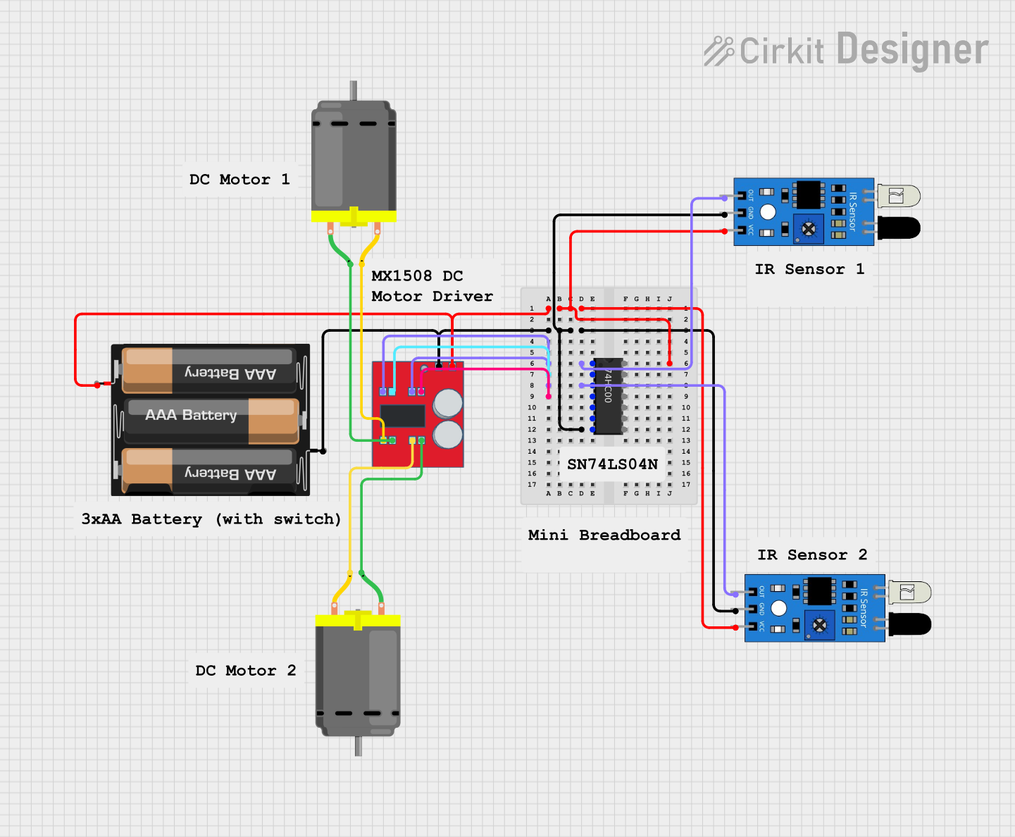
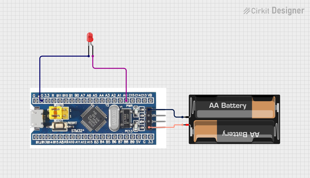
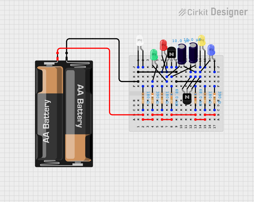

Explore Projects Built with H11AA1
Common Applications and Use Cases
- AC signal detection and isolation
- Zero-crossing detection in AC circuits
- Microcontroller interfacing with high-voltage systems
- Industrial control systems
- Power supply monitoring and feedback
Technical Specifications
Key Technical Details
- Input LED Forward Voltage (VF): 1.2V (typical), 1.5V (maximum)
- Input LED Forward Current (IF): 10mA (typical), 60mA (maximum)
- Output Phototransistor Voltage (VCEO): 30V (maximum)
- Isolation Voltage: 5300 VRMS (minimum)
- CTR (Current Transfer Ratio): 20% to 200% (depending on conditions)
- Operating Temperature Range: -55°C to +100°C
- Package Type: 6-pin DIP
Pin Configuration and Descriptions
The H11AA1 is housed in a 6-pin DIP package. Below is the pinout and description:
| Pin Number | Name | Description |
|---|---|---|
| 1 | Anode (LED1) | Positive terminal of the first internal LED. Connect to the input signal. |
| 2 | Cathode (LED1) | Negative terminal of the first internal LED. Connect to ground. |
| 3 | Anode (LED2) | Positive terminal of the second internal LED. Connect to the input signal. |
| 4 | Cathode (LED2) | Negative terminal of the second internal LED. Connect to ground. |
| 5 | Emitter | Emitter of the phototransistor. Connect to the output circuit. |
| 6 | Collector | Collector of the phototransistor. Connect to the output circuit. |
Usage Instructions
How to Use the H11AA1 in a Circuit
Input Side (LEDs):
- Connect the anodes (Pins 1 and 3) to the AC signal source through appropriate current-limiting resistors.
- Connect the cathodes (Pins 2 and 4) to ground.
- Ensure the input current does not exceed the maximum forward current (60mA).
Output Side (Phototransistor):
- Connect the collector (Pin 6) to the positive supply voltage through a pull-up resistor.
- Connect the emitter (Pin 5) to ground.
- The output signal can be read across the pull-up resistor. When the input LEDs are activated, the phototransistor conducts, pulling the output low.
AC Signal Detection:
- The H11AA1 is designed for AC signals. Both LEDs are connected in reverse parallel internally, allowing the device to detect both positive and negative half-cycles of an AC waveform.
Important Considerations and Best Practices
- Use appropriate current-limiting resistors on the input side to prevent damage to the LEDs.
- Ensure the pull-up resistor on the output side is chosen based on the desired output voltage and current requirements.
- Avoid exceeding the maximum voltage and current ratings to prevent permanent damage to the component.
- For microcontroller interfacing, ensure the output voltage levels are compatible with the microcontroller's input pins.
Example: Interfacing H11AA1 with Arduino UNO
Below is an example of using the H11AA1 to detect an AC signal and interface it with an Arduino UNO:
// Define the input pin for the H11AA1 output
const int optoInputPin = 2; // Connect H11AA1 output to Arduino digital pin 2

void setup() {
  pinMode(optoInputPin, INPUT); // Set the pin as input
  Serial.begin(9600); // Initialize serial communication for debugging
}

void loop() {
  int signalState = digitalRead(optoInputPin); // Read the H11AA1 output state

  if (signalState == HIGH) {
    Serial.println("AC signal detected"); // Print message if signal is detected
  } else {
    Serial.println("No AC signal"); // Print message if no signal is detected
  }

  delay(500); // Add a delay for stability
}
Troubleshooting and FAQs
Common Issues and Solutions
No Output Signal Detected:
- Cause: Incorrect input resistor value or insufficient input current.
- Solution: Verify the current-limiting resistor value and ensure the input current is within the specified range.
Output Signal Always Low:
- Cause: Faulty or damaged H11AA1 component.
- Solution: Replace the H11AA1 and check for proper operation.
Output Signal Always High:
- Cause: Incorrect pull-up resistor value or improper wiring.
- Solution: Verify the pull-up resistor value and ensure correct wiring of the output circuit.
Excessive Heat or Component Damage:
- Cause: Exceeding maximum voltage or current ratings.
- Solution: Double-check the circuit design and ensure all parameters are within the specified limits.
FAQs
Q1: Can the H11AA1 be used for DC signal isolation?
A1: No, the H11AA1 is specifically designed for AC signal isolation due to its internal reverse-parallel LED configuration.
Q2: What is the maximum frequency the H11AA1 can handle?
A2: The H11AA1 is suitable for low-frequency AC signals, typically up to a few kHz. For higher frequencies, consider using a high-speed optocoupler.
Q3: Can I use the H11AA1 for 230V AC mains detection?
A3: Yes, but you must use appropriate current-limiting resistors and ensure proper isolation and safety precautions when working with high voltages.
Q4: How do I calculate the input resistor value?
A4: Use the formula:
[
R = \frac{V_{in} - V_F}{I_F}
]
Where (V_{in}) is the input voltage, (V_F) is the forward voltage of the LED (1.2V typical), and (I_F) is the desired forward current (e.g., 10mA).
By following this documentation, you can effectively integrate the H11AA1 into your electronic projects for reliable AC signal isolation and detection.