How to Use Adafruit 14-segment LED Alphanumeric Backpack White: Examples, Pinouts, and Specs
Introduction
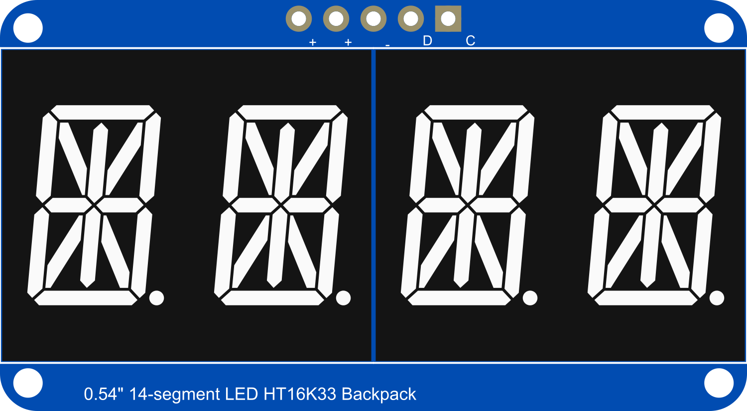
The Adafruit 14-Segment LED Alphanumeric Backpack is a versatile and easy-to-use display module that allows users to add a bright, crisp white LED readout to their projects. With 14 segments per character, it can display numbers, letters, and a variety of symbols, making it suitable for a wide range of applications such as digital clocks, counters, message boards, and any project requiring alphanumeric output.
Explore Projects Built with Adafruit 14-segment LED Alphanumeric Backpack White
Explore Projects Built with Adafruit 14-segment LED Alphanumeric Backpack White
Common Applications and Use Cases
- Digital clocks and timers
- Counter displays
- Message boards for information sharing
- User interfaces for electronic devices
- Scoreboards for games and sports
Technical Specifications
Key Technical Details
- Display Color: White
- Number of Characters: 4
- Character Segments: 14 per character
- Operating Voltage: 3.3V - 5V DC
- Max Current (per segment): 18 mA
- Interface: I2C
- I2C Addresses: 0x70 (default) - 0x77 (selectable with solder jumpers)
Pin Configuration and Descriptions
| Pin Name | Description |
|---|---|
| VCC | Power supply (3.3V - 5V DC) |
| GND | Ground |
| SDA | I2C Data Line |
| SCL | I2C Clock Line |
| ADDR | Address selection (connect to GND or VCC) |
Usage Instructions
How to Use the Component in a Circuit
- Power Connections: Connect the VCC pin to a 3.3V or 5V power supply and the GND pin to the ground of your power supply.
- I2C Connections: Connect the SDA and SCL pins to the I2C data and clock lines on your microcontroller.
- Address Selection: If using multiple displays, solder the ADDR pads to assign unique I2C addresses.
Important Considerations and Best Practices
- Ensure that the power supply voltage matches the operating voltage of the display to prevent damage.
- Use pull-up resistors on the I2C data and clock lines if they are not already present on your microcontroller board.
- When daisy-chaining multiple displays, verify that each display has a unique I2C address.
- Avoid exceeding the maximum current rating per segment to prevent overheating and potential damage to the LEDs.
Example Code for Arduino UNO
#include <Wire.h>
#include <Adafruit_GFX.h>
#include "Adafruit_LEDBackpack.h"

Adafruit_AlphaNum4 alpha4 = Adafruit_AlphaNum4();

void setup() {
  alpha4.begin(0x70);  // initialize the display with its I2C address
}

void loop() {
  alpha4.writeDigitAscii(0, 'H');  // Display 'H' on the first character
  alpha4.writeDigitAscii(1, 'E');  // Display 'E' on the second character
  alpha4.writeDigitAscii(2, 'L');  // Display 'L' on the third character
  alpha4.writeDigitAscii(3, 'P');  // Display 'P' on the fourth character
  alpha4.writeDisplay();           // Send the data to the display
  delay(2000);                     // Wait for 2 seconds
  alpha4.clear();                  // Clear the display
  alpha4.writeDisplay();           // Send the clear command to the display
  delay(500);                      // Wait for half a second
}
Troubleshooting and FAQs
Common Issues
- Display Not Lighting Up: Check the power connections and ensure the I2C lines are properly connected.
- Garbled Characters: Ensure that the I2C address is correctly set and that there are no conflicts on the I2C bus.
- Dim Display: Verify that the power supply is providing adequate voltage and that the current limiting resistors are correctly sized.
Solutions and Tips for Troubleshooting
- Double-check wiring, especially the I2C connections.
- Use the
i2cdetectutility or similar tools to confirm the display's address on the I2C bus. - If using multiple displays, ensure that each one has a unique address by adjusting the ADDR pins.
FAQs
Q: Can I use this display with a 3.3V system?
A: Yes, the display can operate at 3.3V, but the brightness may be reduced compared to 5V operation.
Q: How many of these displays can I chain together?
A: You can chain up to 8 displays using different I2C addresses, from 0x70 to 0x77.
Q: Can I use this display with platforms other than Arduino?
A: Yes, as long as the platform supports I2C communication and you have the necessary libraries or can write your own driver code.