
How to Use Boost converter: Examples, Pinouts, and Specs
 Design with Boost converter in Cirkit Designer
Introduction
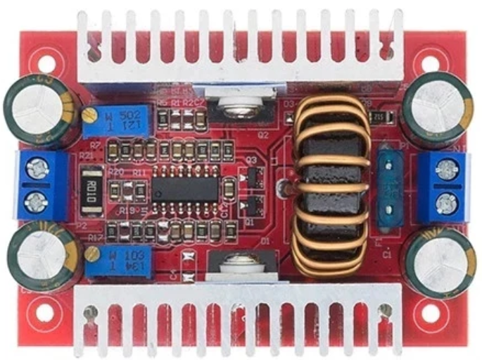
A Boost Converter is a DC-DC power converter that steps up (increases) the input voltage to a higher output voltage while maintaining the same polarity. It operates using an inductor, a switch (typically a transistor), a diode, and a capacitor to achieve efficient voltage conversion. This component is widely used in applications where a higher voltage is required from a lower voltage source, such as in battery-powered devices, renewable energy systems, and automotive electronics.
Explore Projects Built with Boost converter
 Open Project in Cirkit Designer
 Open Project in Cirkit Designer
 Open Project in Cirkit Designer
 Open Project in Cirkit Designer
Explore Projects Built with Boost converter
Open Project in Cirkit DesignerOpen Project in Cirkit DesignerOpen Project in Cirkit DesignerOpen Project in Cirkit DesignerCommon Applications
- Powering high-voltage devices from low-voltage batteries
- Solar power systems to step up panel voltage
- LED drivers
- Electric vehicles and hybrid systems
- Portable electronics requiring efficient power conversion
Technical Specifications
Key Technical Details
| Parameter | Value/Range |
|---|---|
| Input Voltage Range | 2V to 36V (varies by model) |
| Output Voltage Range | 5V to 60V (varies by model) |
| Output Current | Up to 10A (depending on design) |
| Efficiency | 80% to 95% |
| Switching Frequency | 100 kHz to 1 MHz |
| Operating Temperature | -40°C to +85°C |
Pin Configuration and Descriptions
| Pin Name | Description |
|---|---|
| VIN | Input voltage terminal (connect to power source) |
| GND | Ground terminal (common ground) |
| VOUT | Output voltage terminal (connect to load) |
| EN (Enable) | Optional pin to enable/disable the converter |
| FB (Feedback) | Feedback pin for voltage regulation |
Usage Instructions
How to Use the Boost Converter in a Circuit
Connect the Input Voltage (VIN):
Attach the positive terminal of your power source to the VIN pin and the negative terminal to the GND pin.Connect the Output Load (VOUT):
Connect the load (e.g., a motor, LED, or other device) to the VOUT pin. Ensure the load's voltage and current requirements are within the boost converter's output specifications.Set the Output Voltage (if adjustable):
Many boost converters have a potentiometer or feedback pin (FB) to adjust the output voltage. Use a multimeter to measure the output voltage while adjusting the potentiometer.Enable the Converter (if applicable):
If the boost converter has an EN (Enable) pin, ensure it is connected to a HIGH signal (or left floating, depending on the design) to activate the converter.Add External Components (if required):
Some designs may require external capacitors or inductors for optimal performance. Refer to the datasheet for specific recommendations.
Important Considerations and Best Practices
- Input Voltage Range: Ensure the input voltage is within the specified range to avoid damaging the converter.
- Heat Dissipation: Boost converters can generate heat during operation. Use a heatsink or ensure proper ventilation if necessary.
- Output Ripple: Add a capacitor at the output to reduce voltage ripple and stabilize the output.
- Current Limitation: Do not exceed the maximum output current rating to prevent overheating or failure.
- Inductor Selection: If designing your own boost converter, choose an inductor with the appropriate current rating and inductance value.
Example: Using a Boost Converter with Arduino UNO
Below is an example of using a boost converter to power a 12V LED strip from a 5V Arduino UNO power source.
Circuit Connections
- Connect the Arduino's 5V pin to the VIN pin of the boost converter.
- Connect the GND pin of the Arduino to the GND pin of the boost converter.
- Adjust the boost converter's output voltage to 12V using the potentiometer.
- Connect the VOUT pin of the boost converter to the positive terminal of the LED strip.
- Connect the negative terminal of the LED strip to the GND pin of the boost converter.
Arduino Code Example
// This code demonstrates controlling an LED strip powered by a boost converter
// using an Arduino UNO. The LED strip is turned on and off at regular intervals.

const int ledControlPin = 9; // Pin connected to a transistor controlling the LED strip

void setup() {
  pinMode(ledControlPin, OUTPUT); // Set the pin as an output
}

void loop() {
  digitalWrite(ledControlPin, HIGH); // Turn on the LED strip
  delay(1000); // Wait for 1 second
  digitalWrite(ledControlPin, LOW);  // Turn off the LED strip
  delay(1000); // Wait for 1 second
}
Troubleshooting and FAQs
Common Issues and Solutions
No Output Voltage:
- Cause: Input voltage is too low or not connected properly.
- Solution: Verify the input voltage is within the specified range and connections are secure.
Output Voltage is Unstable:
- Cause: Insufficient input or output capacitors.
- Solution: Add capacitors with appropriate values to stabilize the voltage.
Excessive Heat Generation:
- Cause: Overloading the converter or poor ventilation.
- Solution: Reduce the load current or add a heatsink to the converter.
Output Voltage is Incorrect:
- Cause: Feedback pin or potentiometer is not set correctly.
- Solution: Adjust the potentiometer while monitoring the output voltage with a multimeter.
High Output Ripple:
- Cause: Insufficient filtering at the output.
- Solution: Add a low ESR capacitor at the output to reduce ripple.
FAQs
Q: Can I use a boost converter to power a microcontroller?
A: Yes, but ensure the output voltage is stable and within the microcontroller's operating range. Use additional filtering if necessary.
Q: What happens if I exceed the maximum input voltage?
A: Exceeding the input voltage can damage the boost converter. Always stay within the specified range.
Q: Can I use a boost converter with a solar panel?
A: Yes, boost converters are commonly used with solar panels to step up the voltage to a usable level. Ensure the input voltage and current are within the converter's specifications.
Q: How do I calculate the required inductor value for a custom boost converter?
A: Use the formula:
[
L = \frac{(V_{in} \cdot (V_{out} - V_{in}))}{I_{out} \cdot f \cdot V_{out}}
]
where ( V_{in} ) is the input voltage, ( V_{out} ) is the output voltage, ( I_{out} ) is the output current, and ( f ) is the switching frequency.
This concludes the documentation for the Boost Converter.