How to Use 24/5v Buck: Examples, Pinouts, and Specs
Introduction
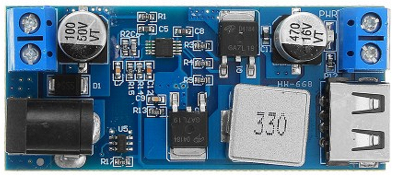
The 24/5V Buck Converter, manufactured by Arduino (Part ID: UNO), is a DC-DC step-down voltage regulator designed to efficiently convert a 24V input to a stable 5V output. This component is ideal for powering low-voltage devices from higher-voltage sources, ensuring minimal energy loss and high efficiency. Its compact design and reliable performance make it a popular choice for embedded systems, IoT devices, and other electronics projects.
Explore Projects Built with 24/5v Buck


Explore Projects Built with 24/5v Buck
Common Applications and Use Cases
- Powering 5V microcontrollers (e.g., Arduino boards, Raspberry Pi)
- Supplying power to sensors, modules, and peripherals in embedded systems
- Battery-powered devices requiring efficient voltage regulation
- Industrial automation systems with 24V power rails
- Robotics and motor control circuits
Technical Specifications
The following table outlines the key technical details of the 24/5V Buck Converter:
| Parameter | Value |
|---|---|
| Input Voltage Range | 7V to 24V |
| Output Voltage | 5V (fixed) |
| Output Current | Up to 3A |
| Efficiency | Up to 95% |
| Switching Frequency | 150 kHz |
| Operating Temperature | -40°C to +85°C |
| Dimensions | 25mm x 20mm x 10mm |
Pin Configuration and Descriptions
The 24/5V Buck Converter has the following pin configuration:
| Pin Name | Description |
|---|---|
| VIN | Input voltage pin (connect to 7V-24V power source) |
| GND | Ground pin (common ground for input and output) |
| VOUT | Regulated 5V output pin (connect to load) |
Usage Instructions
How to Use the Component in a Circuit
Connect the Input Voltage:
- Attach the VIN pin to a DC power source with a voltage between 7V and 24V.
- Ensure the power source can supply sufficient current for your load.
Connect the Ground:
- Connect the GND pin to the ground of your circuit. This serves as the common reference point.
Connect the Output Voltage:
- Attach the VOUT pin to the device or circuit requiring a 5V power supply.
- Ensure the load does not exceed the maximum output current of 3A.
Power On:
- Turn on the input power source. The buck converter will regulate the input voltage to provide a stable 5V output.
Important Considerations and Best Practices
- Input Voltage Range: Ensure the input voltage is within the specified range (7V-24V). Exceeding this range may damage the component.
- Heat Dissipation: For high-current loads, consider adding a heatsink or ensuring proper ventilation to prevent overheating.
- Capacitor Placement: Place decoupling capacitors (e.g., 10µF and 0.1µF) near the input and output pins to reduce noise and improve stability.
- Polarity Protection: Double-check the polarity of the input and output connections to avoid damage.
- Load Requirements: Ensure the connected load does not exceed the maximum output current of 3A.
Example: Using the 24/5V Buck Converter with an Arduino UNO
The following example demonstrates how to use the 24/5V Buck Converter to power an Arduino UNO from a 24V power source.
Circuit Connections
- Connect the VIN pin of the buck converter to the 24V power source.
- Connect the GND pin of the buck converter to the ground of the power source.
- Connect the VOUT pin of the buck converter to the 5V pin of the Arduino UNO.
- Connect the GND pin of the buck converter to the GND pin of the Arduino UNO.
Sample Code
The following Arduino code blinks an LED connected to pin 13, powered by the 24/5V Buck Converter:
// Blink an LED connected to pin 13
// Ensure the Arduino UNO is powered via the 24/5V Buck Converter

void setup() {
  pinMode(13, OUTPUT); // Set pin 13 as an output
}

void loop() {
  digitalWrite(13, HIGH); // Turn the LED on
  delay(1000);            // Wait for 1 second
  digitalWrite(13, LOW);  // Turn the LED off
  delay(1000);            // Wait for 1 second
}
Troubleshooting and FAQs
Common Issues and Solutions
No Output Voltage:
- Cause: Input voltage is below 7V or improperly connected.
- Solution: Verify the input voltage and connections. Ensure the power source is functional.
Overheating:
- Cause: Excessive load current or poor ventilation.
- Solution: Reduce the load current or add a heatsink to the buck converter.
Output Voltage Fluctuations:
- Cause: Insufficient decoupling capacitors or noisy input power.
- Solution: Add decoupling capacitors (e.g., 10µF and 0.1µF) near the input and output pins.
Damaged Component:
- Cause: Input voltage exceeded 24V or incorrect polarity.
- Solution: Replace the component and ensure proper voltage and polarity in future use.
FAQs
Q: Can I use the 24/5V Buck Converter to power multiple devices?
A: Yes, as long as the total current draw does not exceed 3A.
Q: Is the output voltage adjustable?
A: No, the output voltage is fixed at 5V.
Q: Can I use this converter with a battery as the input source?
A: Yes, as long as the battery voltage is within the 7V-24V range.
Q: Does the converter have built-in short-circuit protection?
A: Some models may include short-circuit protection. Refer to the specific datasheet for details.