How to Use 8X8 20 MM YELLOW-GREEN LED MATRIX: Examples, Pinouts, and Specs
Introduction
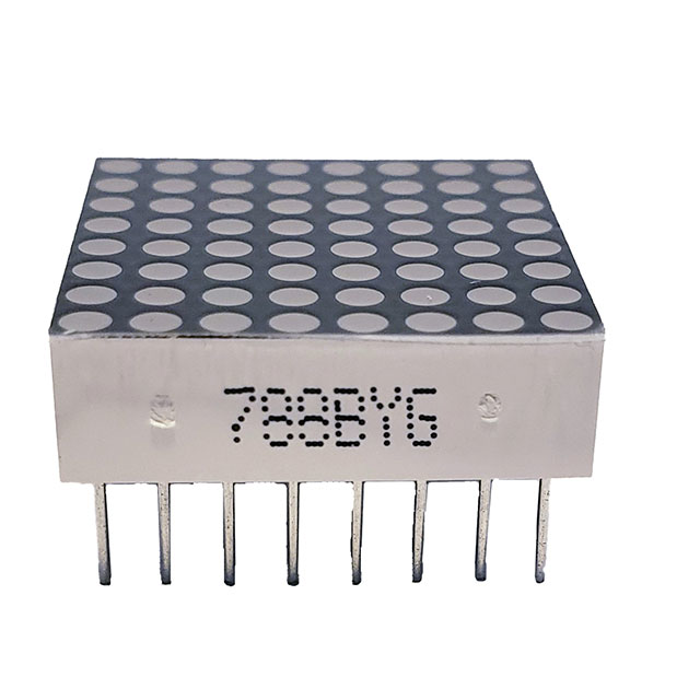
The 8x8 20mm Yellow-Green LED Matrix by Gearbox Labs (Part ID: 4166-PART8X820MMYELLOW-GREENLEDMATRIX-ND) is a versatile display component consisting of 64 LEDs arranged in an 8x8 grid. This matrix emits a bright yellow-green light, making it ideal for displaying characters, symbols, and simple graphics in various electronic devices. Common applications include digital clocks, message boards, and status indicators.
Explore Projects Built with 8X8 20 MM YELLOW-GREEN LED MATRIX


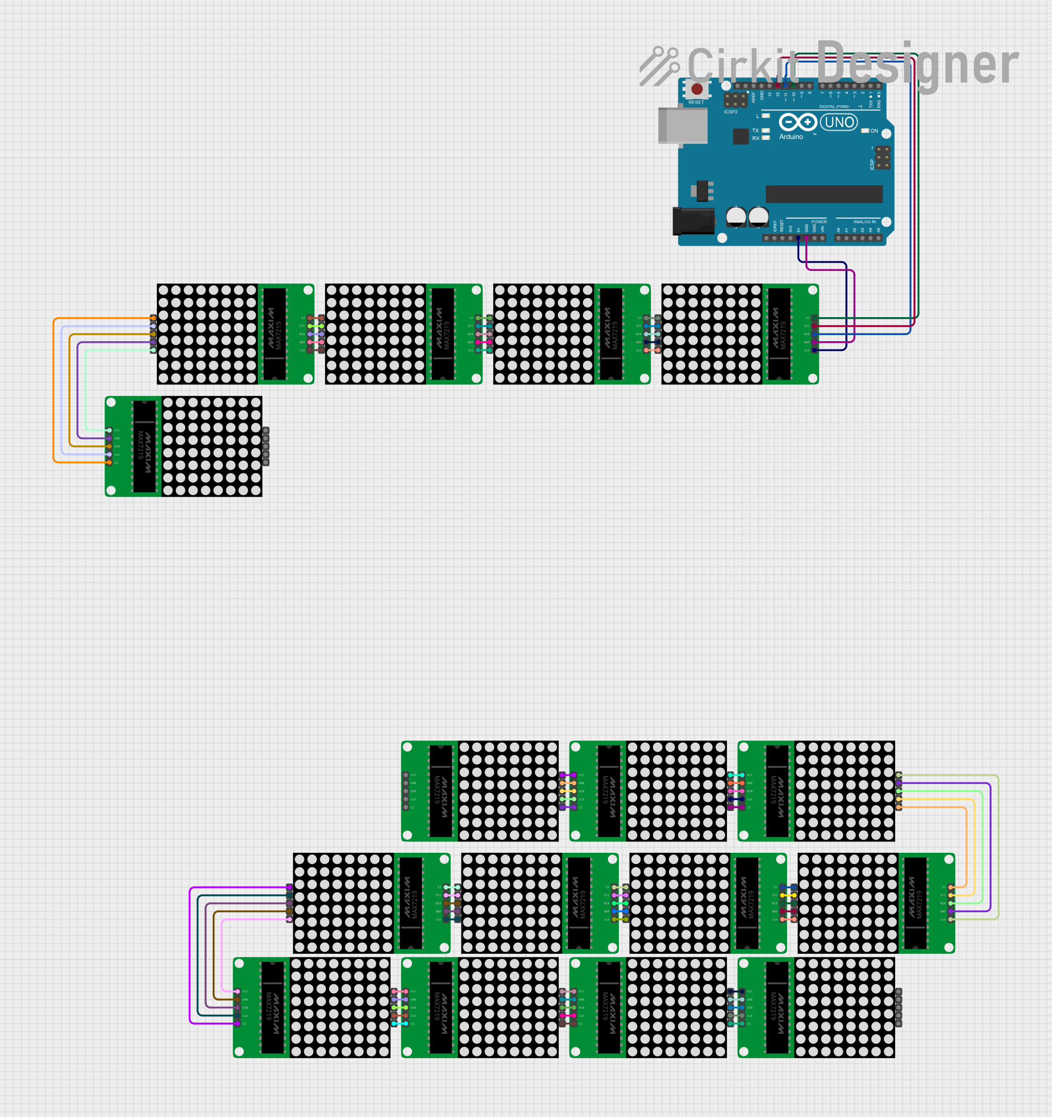
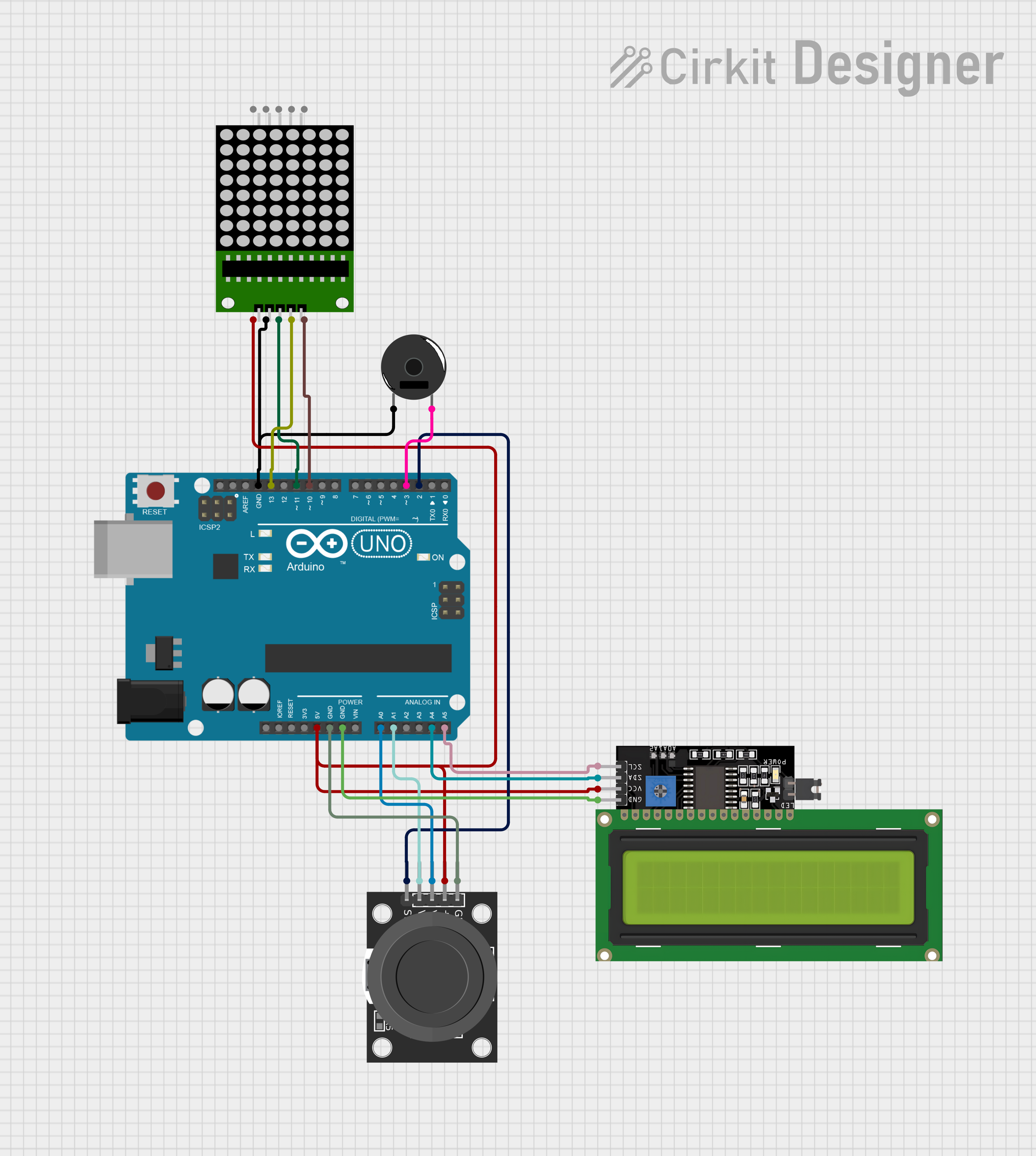
Explore Projects Built with 8X8 20 MM YELLOW-GREEN LED MATRIX
Technical Specifications
Key Technical Details
| Parameter | Value |
|---|---|
| LED Color | Yellow-Green |
| LED Size | 20mm |
| Matrix Dimensions | 8x8 (64 LEDs) |
| Forward Voltage | 2.0V - 2.2V per LED |
| Forward Current | 20mA per LED |
| Power Dissipation | 50mW per LED |
| Viewing Angle | 120 degrees |
| Operating Temperature | -40°C to +85°C |
Pin Configuration and Descriptions
The 8x8 LED matrix has 16 pins, with each pin corresponding to either a row or a column in the matrix. The following table describes the pin configuration:
| Pin Number | Description | Function |
|---|---|---|
| 1 | Row 1 | Connect to row driver |
| 2 | Row 2 | Connect to row driver |
| 3 | Row 3 | Connect to row driver |
| 4 | Row 4 | Connect to row driver |
| 5 | Row 5 | Connect to row driver |
| 6 | Row 6 | Connect to row driver |
| 7 | Row 7 | Connect to row driver |
| 8 | Row 8 | Connect to row driver |
| 9 | Column 1 | Connect to column driver |
| 10 | Column 2 | Connect to column driver |
| 11 | Column 3 | Connect to column driver |
| 12 | Column 4 | Connect to column driver |
| 13 | Column 5 | Connect to column driver |
| 14 | Column 6 | Connect to column driver |
| 15 | Column 7 | Connect to column driver |
| 16 | Column 8 | Connect to column driver |
Usage Instructions
How to Use the Component in a Circuit
To use the 8x8 LED matrix in a circuit, you need to connect the row and column pins to appropriate drivers. A common approach is to use shift registers or LED driver ICs to control the matrix. Below is a basic example of connecting the matrix to an Arduino UNO using two 74HC595 shift registers:
Connect the Matrix to the Shift Registers:
- Connect the row pins (1-8) to the outputs of the first 74HC595.
- Connect the column pins (9-16) to the outputs of the second 74HC595.
Connect the Shift Registers to the Arduino:
- Connect the data pin (DS) of the first 74HC595 to Arduino pin 11.
- Connect the clock pin (SH_CP) of both 74HC595s to Arduino pin 12.
- Connect the latch pin (ST_CP) of both 74HC595s to Arduino pin 8.
Power the Circuit:
- Connect the VCC and GND pins of the 74HC595s to the 5V and GND pins of the Arduino.
Important Considerations and Best Practices
- Current Limiting Resistors: Use appropriate current-limiting resistors to prevent damage to the LEDs. Typically, a 220Ω resistor is used in series with each row or column.
- Multiplexing: To control the matrix efficiently, use multiplexing techniques to light up one row or column at a time.
- Heat Dissipation: Ensure proper heat dissipation, especially if multiple LEDs are lit simultaneously.
Example Arduino Code
// Include the Shift Register library
#include <ShiftRegister74HC595.h>

// Create a ShiftRegister74HC595 object
ShiftRegister74HC595<2> sr(8, 11, 12); // (number of shift registers, data pin, clock pin, latch pin)

void setup() {
  // Initialize the shift register
  sr.setAllLow();
}

void loop() {
  // Example: Light up the first row
  uint8_t row = 0b00000001; // Binary representation of the first row
  uint8_t col = 0b11111111; // Binary representation of all columns

  // Set the row and column data
  sr.set(0, row); // Set the first shift register (rows)
  sr.set(1, col); // Set the second shift register (columns)

  delay(1000); // Wait for 1 second

  // Turn off all LEDs
  sr.setAllLow();
  delay(1000); // Wait for 1 second
}
Troubleshooting and FAQs
Common Issues Users Might Face
LEDs Not Lighting Up:
- Solution: Check all connections and ensure that the shift registers are properly connected to the Arduino. Verify that the power supply is adequate.
Dim LEDs:
- Solution: Ensure that the current-limiting resistors are of the correct value. Check the power supply voltage and current ratings.
Flickering LEDs:
- Solution: Implement proper multiplexing techniques and ensure that the refresh rate is high enough to avoid visible flicker.
Solutions and Tips for Troubleshooting
- Check Connections: Ensure all connections are secure and correctly mapped according to the pin configuration.
- Verify Code: Double-check the Arduino code for any logical errors or incorrect pin assignments.
- Use a Multimeter: Measure the voltage and current at various points in the circuit to identify any discrepancies.
By following this documentation, users should be able to effectively integrate and troubleshoot the 8x8 20mm Yellow-Green LED Matrix in their projects. Whether you are a beginner or an experienced user, this guide provides the necessary information to get started and ensure optimal performance.