How to Use TFT ST7789V 2.8': Examples, Pinouts, and Specs
Introduction
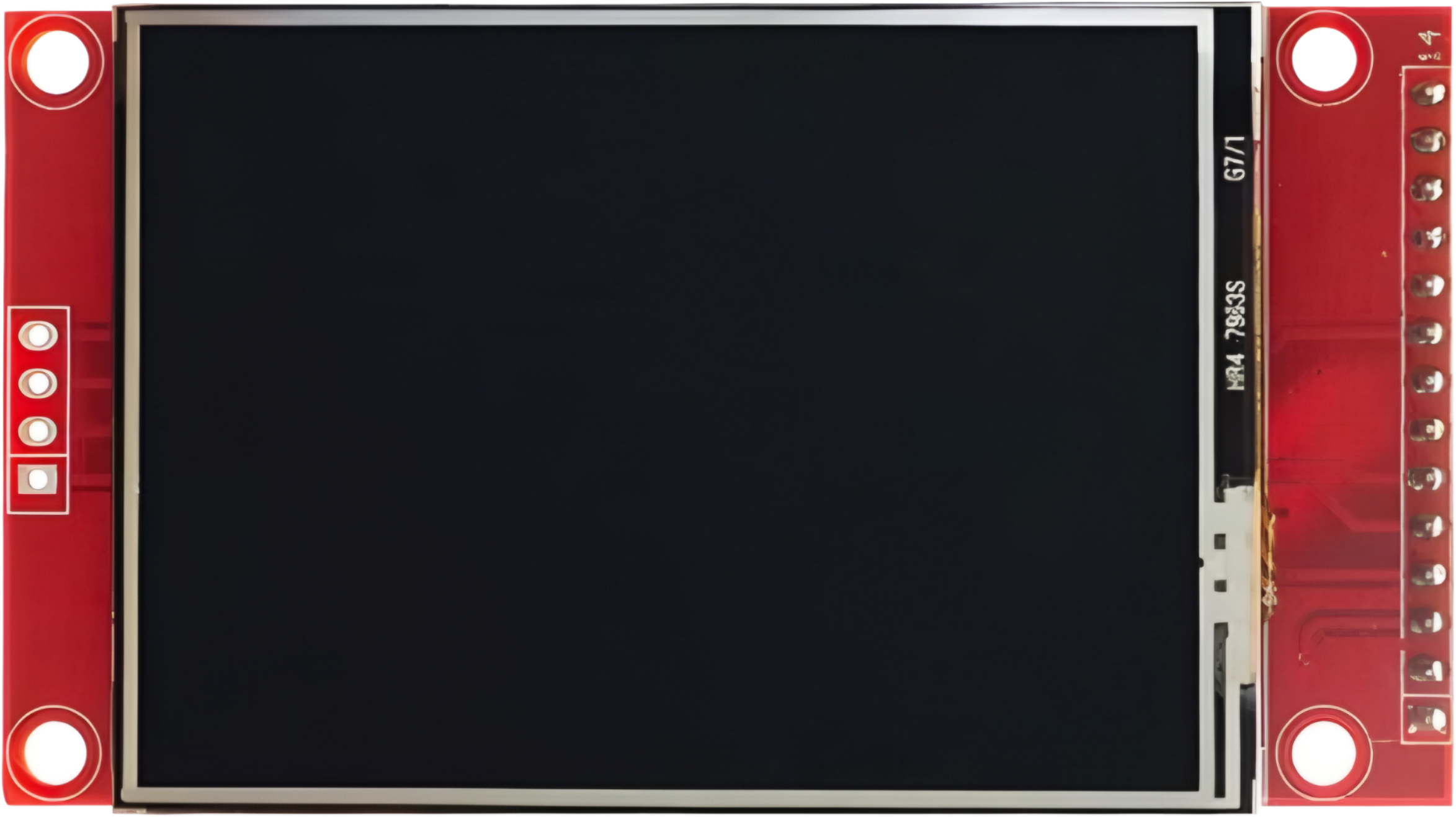
The TFT ST7789V 2.8' is a 2.8-inch thin-film transistor (TFT) display module that utilizes the ST7789V driver. This display is known for its high resolution, vibrant color output, and compact size, making it ideal for a wide range of embedded applications. It supports 240x320 pixel resolution and can display up to 262K colors, providing excellent visual clarity for graphical interfaces.
Explore Projects Built with TFT ST7789V 2.8'


Explore Projects Built with TFT ST7789V 2.8'
Common Applications and Use Cases
- Handheld devices and portable electronics
- IoT dashboards and smart home displays
- Wearable devices
- Industrial control panels
- Educational and hobbyist projects with microcontrollers (e.g., Arduino, Raspberry Pi)
Technical Specifications
Below are the key technical details and pin configuration for the TFT ST7789V 2.8' module:
Key Technical Details
| Parameter | Specification |
|---|---|
| Display Type | TFT LCD |
| Driver IC | ST7789V |
| Screen Size | 2.8 inches |
| Resolution | 240x320 pixels |
| Color Depth | 262K colors |
| Interface | SPI (4-wire) |
| Operating Voltage | 3.3V |
| Backlight Voltage | 3.0V to 3.6V |
| Operating Temperature | -20°C to 70°C |
| Viewing Angle | 80° (all directions) |
Pin Configuration and Descriptions
The TFT ST7789V module typically has an 8-pin interface. Below is the pinout description:
| Pin No. | Name | Description |
|---|---|---|
| 1 | GND | Ground connection |
| 2 | VCC | Power supply (3.3V) |
| 3 | SCL | Serial Clock Line (SPI clock input) |
| 4 | SDA | Serial Data Line (SPI data input/output) |
| 5 | RES | Reset pin (active low, used to reset the display) |
| 6 | DC | Data/Command control pin (high for data, low for command) |
| 7 | CS | Chip Select (active low, used to enable communication with the display) |
| 8 | BLK | Backlight control (connect to 3.3V or PWM for brightness control) |
Usage Instructions
How to Use the Component in a Circuit
- Power Supply: Connect the
VCCpin to a 3.3V power source and theGNDpin to ground. - SPI Communication: Connect the
SCL(clock) andSDA(data) pins to the corresponding SPI pins on your microcontroller. - Control Pins:
- Connect the
RESpin to a GPIO pin on your microcontroller for resetting the display. - Use the
DCpin to differentiate between data and command signals. - Connect the
CSpin to a GPIO pin to enable or disable communication with the display.
- Connect the
- Backlight: Connect the
BLKpin to 3.3V for full brightness or to a PWM pin for adjustable brightness.
Important Considerations and Best Practices
- Voltage Levels: Ensure all signal lines operate at 3.3V logic levels. Use a level shifter if your microcontroller operates at 5V.
- Capacitors: Add decoupling capacitors (e.g., 0.1µF) near the power pins to stabilize the power supply.
- Reset Timing: Hold the
RESpin low for at least 10ms during initialization to ensure proper startup. - SPI Speed: Use an SPI clock speed of up to 15MHz for optimal performance.
Example Code for Arduino UNO
Below is an example of how to interface the TFT ST7789V with an Arduino UNO using the Adafruit ST7789 library:
#include <Adafruit_GFX.h>    // Core graphics library
#include <Adafruit_ST7789.h> // ST7789 driver library
#include <SPI.h>             // SPI library

// Define pin connections
#define TFT_CS    10  // Chip Select pin
#define TFT_RST   9   // Reset pin
#define TFT_DC    8   // Data/Command pin

// Initialize the display object
Adafruit_ST7789 tft = Adafruit_ST7789(TFT_CS, TFT_DC, TFT_RST);

void setup() {
  // Initialize serial communication for debugging
  Serial.begin(9600);
  Serial.println("TFT ST7789V Test");

  // Initialize the display
  tft.init(240, 320); // Initialize with 240x320 resolution
  tft.setRotation(1); // Set display orientation (0-3)

  // Fill the screen with a color
  tft.fillScreen(ST77XX_BLACK);

  // Draw a simple message
  tft.setTextColor(ST77XX_WHITE);
  tft.setTextSize(2);
  tft.setCursor(10, 10);
  tft.println("Hello, ST7789!");
}

void loop() {
  // Add your code here to update the display
}
Notes:
- Install the Adafruit GFX and Adafruit ST7789 libraries via the Arduino Library Manager before running the code.
- Adjust the pin definitions (
TFT_CS,TFT_RST,TFT_DC) to match your wiring.
Troubleshooting and FAQs
Common Issues and Solutions
Display Not Turning On:
- Verify the power connections (
VCCandGND). - Ensure the backlight pin (
BLK) is connected to 3.3V or a PWM signal.
- Verify the power connections (
No Output on the Screen:
- Check the SPI connections (
SCL,SDA,CS,DC). - Ensure the
RESpin is properly connected and initialized in the code.
- Check the SPI connections (
Flickering or Distorted Display:
- Reduce the SPI clock speed in the code.
- Add decoupling capacitors near the power pins.
Incorrect Colors or Orientation:
- Verify the initialization code and ensure the correct rotation is set using
tft.setRotation().
- Verify the initialization code and ensure the correct rotation is set using
FAQs
Q: Can I use this display with a 5V microcontroller?
A: Yes, but you must use level shifters to convert the 5V logic signals to 3.3V.
Q: What is the maximum SPI clock speed supported?
A: The ST7789V supports SPI clock speeds up to 15MHz.
Q: Can I control the backlight brightness?
A: Yes, connect the BLK pin to a PWM-capable pin on your microcontroller to adjust brightness.
Q: Is this display compatible with Raspberry Pi?
A: Yes, the display can be used with Raspberry Pi via SPI, but you may need to configure the SPI interface in the Raspberry Pi OS.
This concludes the documentation for the TFT ST7789V 2.8' module.