How to Use ESP32C3: Examples, Pinouts, and Specs
Introduction
The ESP32C3 is a low-power system on a chip (SoC) with integrated Wi-Fi and Bluetooth capabilities, designed specifically for Internet of Things (IoT) applications. It is built on a RISC-V architecture, offering high performance and efficiency. The ESP32C3 features multiple GPIO pins, supports various communication protocols, and is well-suited for smart devices, sensor networks, and other connected applications.
Explore Projects Built with ESP32C3


Explore Projects Built with ESP32C3
Common Applications and Use Cases
- Smart home devices (e.g., smart lights, thermostats)
- Wearable technology
- Industrial IoT systems
- Wireless sensor networks
- Remote monitoring and control systems
- Low-power Bluetooth and Wi-Fi applications
Technical Specifications
Key Technical Details
| Parameter | Value |
|---|---|
| Architecture | RISC-V (32-bit) |
| Clock Speed | Up to 160 MHz |
| Flash Memory | 4 MB (varies by module) |
| SRAM | 400 KB |
| Wi-Fi | IEEE 802.11 b/g/n (2.4 GHz) |
| Bluetooth | Bluetooth 5.0 LE |
| GPIO Pins | 22 (multipurpose) |
| Operating Voltage | 3.0V to 3.6V |
| Power Consumption | Ultra-low power in deep sleep mode |
| Communication Protocols | UART, SPI, I2C, I2S, PWM, ADC, DAC |
| Operating Temperature | -40°C to 85°C |
Pin Configuration and Descriptions
The ESP32C3 has a total of 22 GPIO pins, which can be configured for various functions. Below is a table of the most commonly used pins and their descriptions:
| Pin Number | Pin Name | Functionality |
|---|---|---|
| 1 | GPIO0 | General-purpose I/O, boot mode selection |
| 2 | GPIO1 | General-purpose I/O, UART TX |
| 3 | GPIO2 | General-purpose I/O, ADC, PWM |
| 4 | GPIO3 | General-purpose I/O, UART RX |
| 5 | GPIO4 | General-purpose I/O, ADC, PWM |
| 6 | GPIO5 | General-purpose I/O, SPI |
| 7 | GPIO6 | General-purpose I/O, I2C SDA |
| 8 | GPIO7 | General-purpose I/O, I2C SCL |
| 9 | GPIO8 | General-purpose I/O, ADC, PWM |
| 10 | GPIO9 | General-purpose I/O, ADC, PWM |
| 11 | GPIO10 | General-purpose I/O, SPI |
| 12 | GPIO11 | General-purpose I/O, SPI |
| 13 | GPIO12 | General-purpose I/O, ADC, PWM |
| 14 | GPIO13 | General-purpose I/O, ADC, PWM |
| 15 | GPIO14 | General-purpose I/O, UART TX |
| 16 | GPIO15 | General-purpose I/O, UART RX |
| 17 | GPIO16 | General-purpose I/O, ADC, PWM |
| 18 | GPIO17 | General-purpose I/O, ADC, PWM |
| 19 | GPIO18 | General-purpose I/O, SPI |
| 20 | GPIO19 | General-purpose I/O, SPI |
| 21 | GPIO20 | General-purpose I/O, ADC, PWM |
| 22 | GPIO21 | General-purpose I/O, ADC, PWM |
Usage Instructions
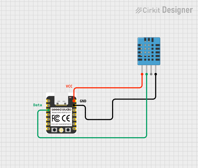
How to Use the ESP32C3 in a Circuit
- Power Supply: Ensure the ESP32C3 is powered with a stable voltage between 3.0V and 3.6V. Use a voltage regulator if necessary.
- GPIO Configuration: Configure the GPIO pins for the desired functionality (e.g., input, output, ADC, PWM).
- Communication Protocols: Use the appropriate communication protocol (e.g., UART, SPI, I2C) for interfacing with other devices.
- Programming: The ESP32C3 can be programmed using the Arduino IDE, ESP-IDF, or other compatible development environments.
Important Considerations and Best Practices
- Boot Mode: GPIO0 is used for boot mode selection. Ensure it is properly configured during programming.
- Deep Sleep Mode: Utilize the deep sleep mode for ultra-low power consumption in battery-powered applications.
- Pull-up/Pull-down Resistors: Use external pull-up or pull-down resistors for GPIO pins as needed.
- Antenna Placement: Ensure proper placement of the onboard antenna for optimal Wi-Fi and Bluetooth performance.
Example Code for Arduino UNO
Below is an example of how to use the ESP32C3 with the Arduino IDE to blink an LED connected to GPIO2:
// Define the GPIO pin for the LED
#define LED_PIN 2

void setup() {
  // Initialize the GPIO pin as an output
  pinMode(LED_PIN, OUTPUT);
}

void loop() {
  // Turn the LED on
  digitalWrite(LED_PIN, HIGH);
  delay(1000); // Wait for 1 second

  // Turn the LED off
  digitalWrite(LED_PIN, LOW);
  delay(1000); // Wait for 1 second
}
Troubleshooting and FAQs
Common Issues and Solutions
ESP32C3 Not Connecting to Wi-Fi:
- Ensure the correct SSID and password are used in the code.
- Check the signal strength of the Wi-Fi network.
- Verify that the ESP32C3 is within range of the Wi-Fi router.
GPIO Pins Not Responding:
- Confirm that the pins are properly configured in the code (e.g., input, output).
- Check for loose connections or faulty wiring.
- Ensure that the GPIO pin is not being used for another function.
Programming Errors:
- Verify that the correct board and port are selected in the Arduino IDE.
- Ensure that the ESP32C3 is in boot mode during programming (hold GPIO0 low).
High Power Consumption:
- Use deep sleep mode to reduce power consumption.
- Disable unused peripherals in the code.
FAQs
Q: Can the ESP32C3 be powered by a 5V source?
A: No, the ESP32C3 operates at 3.0V to 3.6V. Use a voltage regulator to step down a 5V source.
Q: Does the ESP32C3 support both Wi-Fi and Bluetooth simultaneously?
A: Yes, the ESP32C3 can use both Wi-Fi and Bluetooth simultaneously, but performance may vary depending on the application.
Q: How do I reset the ESP32C3?
A: Press the reset button on the development board or toggle the EN (enable) pin.
Q: Can I use the ESP32C3 with batteries?
A: Yes, the ESP32C3 is designed for low-power applications and can be powered by batteries. Use deep sleep mode to extend battery life.