How to Use RGB: Examples, Pinouts, and Specs
Introduction
An RGB LED is a light-emitting diode capable of producing a wide range of colors by combining the three primary colors of light: Red, Green, and Blue. Each color is controlled by an individual LED within the component, and the intensity of each LED can be adjusted to create various colors. RGB LEDs are widely used in electronic displays, decorative lighting, status indicators, and other applications requiring dynamic color control.
Explore Projects Built with RGB

Explore Projects Built with RGB
Common Applications
- LED displays and screens
- Smart lighting systems
- Decorative and ambient lighting
- Status indicators in electronic devices
- Prototyping and DIY electronics projects
Technical Specifications
Below are the key technical details for a common RGB LED:
| Parameter | Value |
|---|---|
| Forward Voltage (Red) | 1.8V - 2.2V |
| Forward Voltage (Green) | 3.0V - 3.2V |
| Forward Voltage (Blue) | 3.0V - 3.2V |
| Forward Current | 20mA (per color) |
| Maximum Power | ~60mW (combined for all colors) |
| Viewing Angle | 120° |
| Package Type | 5mm or 10mm (common sizes) |
Pin Configuration
RGB LEDs typically have four pins: one for each color (Red, Green, Blue) and a common pin. The common pin can either be anode (positive) or cathode (negative), depending on the type of RGB LED.
| Pin Number | Pin Name | Description |
|---|---|---|
| 1 | Red | Controls the red LED |
| 2 | Common Anode/Cathode | Shared pin for all LEDs (positive or negative) |
| 3 | Green | Controls the green LED |
| 4 | Blue | Controls the blue LED |
Usage Instructions
How to Use an RGB LED in a Circuit
- Identify the Pin Configuration: Determine whether your RGB LED is common anode or common cathode. This information is crucial for proper wiring.
- Connect the Common Pin:
- For a common anode RGB LED, connect the common pin to the positive voltage supply (Vcc).
- For a common cathode RGB LED, connect the common pin to ground (GND).
- Use Current-Limiting Resistors: Connect a resistor (typically 220Ω to 330Ω) in series with each color pin to limit the current and prevent damage to the LED.
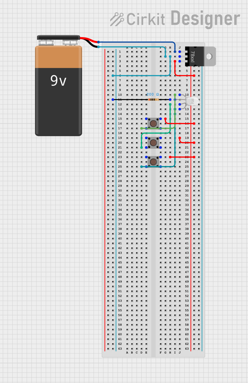
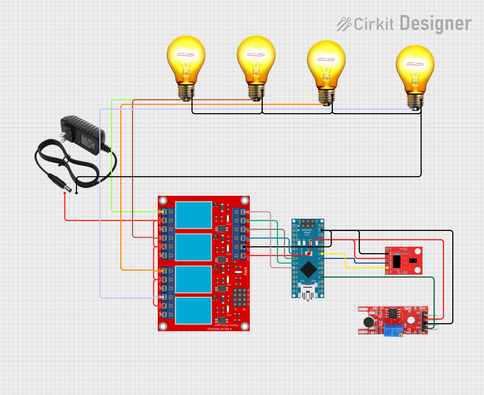
- Control the Colors: Use a microcontroller (e.g., Arduino) or a simple circuit with switches or potentiometers to adjust the intensity of each color.
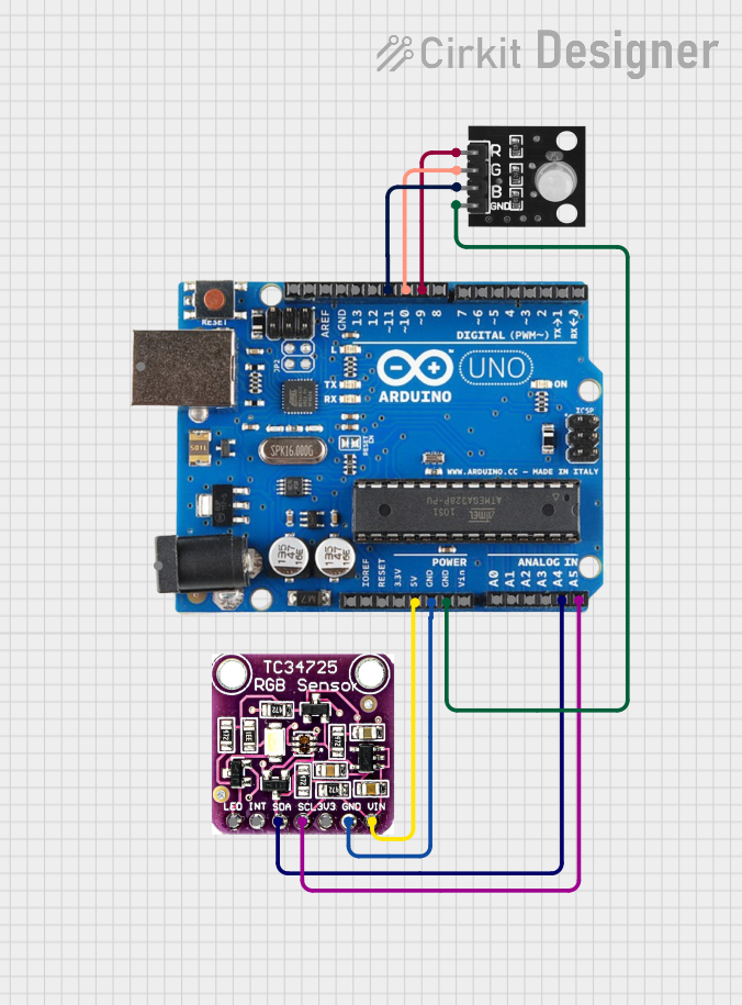
Example Circuit with Arduino UNO
Below is an example of how to connect and control an RGB LED using an Arduino UNO:
Circuit Connections
- Connect the common pin of the RGB LED to 5V (common anode) or GND (common cathode).
- Connect the Red, Green, and Blue pins to Arduino digital pins (e.g., D9, D10, D11) through 220Ω resistors.
Arduino Code
// Define the pins for the RGB LED
const int redPin = 9;    // Red LED connected to pin 9
const int greenPin = 10; // Green LED connected to pin 10
const int bluePin = 11;  // Blue LED connected to pin 11

void setup() {
  // Set the RGB pins as output
  pinMode(redPin, OUTPUT);
  pinMode(greenPin, OUTPUT);
  pinMode(bluePin, OUTPUT);
}

void loop() {
  // Example: Cycle through colors
  setColor(255, 0, 0); // Red
  delay(1000);
  setColor(0, 255, 0); // Green
  delay(1000);
  setColor(0, 0, 255); // Blue
  delay(1000);
  setColor(255, 255, 0); // Yellow
  delay(1000);
  setColor(0, 255, 255); // Cyan
  delay(1000);
  setColor(255, 0, 255); // Magenta
  delay(1000);
  setColor(255, 255, 255); // White
  delay(1000);
}

// Function to set the RGB LED color
void setColor(int red, int green, int blue) {
  analogWrite(redPin, red);   // Set red intensity (0-255)
  analogWrite(greenPin, green); // Set green intensity (0-255)
  analogWrite(bluePin, blue);  // Set blue intensity (0-255)
}
Important Considerations
- Resistor Selection: Always use appropriate resistors to limit current and protect the LED.
- Power Supply: Ensure the power supply voltage matches the LED's requirements.
- PWM Control: Use PWM (Pulse Width Modulation) to control the brightness of each color for smooth color transitions.
Troubleshooting and FAQs
Common Issues
LED Not Lighting Up:
- Check the pin connections and ensure the common pin is correctly connected to Vcc or GND.
- Verify that the current-limiting resistors are properly connected.
- Ensure the power supply is functioning and providing the correct voltage.
Incorrect Colors Displayed:
- Double-check the wiring of the Red, Green, and Blue pins.
- Verify the code logic if using a microcontroller.
LED Flickering:
- Ensure stable power supply and proper grounding.
- If using PWM, verify the frequency and duty cycle settings.
FAQs
Q: Can I use an RGB LED without a microcontroller?
A: Yes, you can use switches, potentiometers, or a simple circuit with resistors to control the colors manually.
Q: What is the difference between common anode and common cathode RGB LEDs?
A: In a common anode RGB LED, the common pin is connected to the positive voltage (Vcc), while in a common cathode RGB LED, the common pin is connected to ground (GND).
Q: How do I create custom colors with an RGB LED?
A: By adjusting the intensity of the Red, Green, and Blue LEDs using PWM, you can mix colors to create a wide spectrum of custom colors.