Cirkit Designer Logo
Cirkit Designer
Your all-in-one circuit design IDE
Home / 
Component Documentation

How to Use RS232 to TTL converter: Examples, Pinouts, and Specs

Image of RS232 to TTL converter
Cirkit Designer LogoDesign with RS232 to TTL converter in Cirkit Designer

Introduction

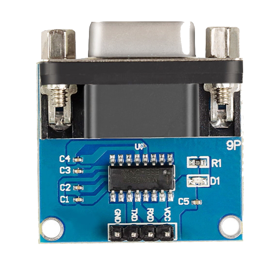
The RS232 to TTL converter by CentIoT, featuring the MAX3232 chip, is an essential device for enabling communication between RS232-compatible devices and those using Transistor-Transistor Logic (TTL) signaling. This converter is widely used in serial communication applications such as interfacing microcontrollers, like Arduino, with RS232 devices like modems, serial monitors, and PCs.

Explore Projects Built with RS232 to TTL converter

Use Cirkit Designer to design, explore, and prototype these projects online. Some projects support real-time simulation. Click "Open Project" to start designing instantly!
Arduino UNO and Relay-Controlled RS485 Communication System
Image of Diagrama: A project utilizing RS232 to TTL converter in a practical application
This circuit features an Arduino UNO microcontroller interfaced with a 4-channel relay module and a UART TTL to RS485 converter. The Arduino controls the relays via digital pins and communicates with the RS485 converter for serial communication, enabling control of external devices and communication over long distances.
Cirkit Designer LogoOpen Project in Cirkit Designer
Arduino UNO RS232 Serial Communication Interface
Image of Reddit Help - RS232 Serial Communication With Digital Scale: A project utilizing RS232 to TTL converter in a practical application
This circuit connects an Arduino UNO to an RS232 to Serial Converter, allowing the Arduino to communicate with RS232-compatible devices. The Arduino's digital pins D10 and D11 are used for RX and TX communication, respectively, and are interfaced with the corresponding TX and RX pins of the RS232 converter. The embedded code on the Arduino sets up a software serial port for communication with the RS232 converter and relays data between the standard serial port and the software serial port.
Cirkit Designer LogoOpen Project in Cirkit Designer
FTDI to UART Adapter with J26 Connector
Image of J26 CLOSEUP: A project utilizing RS232 to TTL converter in a practical application
This circuit connects an FTDI USB-to-serial converter to a standard serial interface via a J26 connector. It facilitates serial communication by linking the ground, transmit, receive, data terminal ready, and request to send signals between the FTDI chip and the J26 connector.
Cirkit Designer LogoOpen Project in Cirkit Designer
Arduino UNO and MAX 3232 Module Controlled NE-1000 Pump System
Image of NE-1000 RS232: A project utilizing RS232 to TTL converter in a practical application
This circuit features an Arduino UNO microcontroller interfaced with a MAX 3232 module for serial communication. The Arduino provides power and ground to the MAX 3232, and the two devices communicate via the TxD and RxD pins. The setup is likely intended for serial data transmission between the Arduino and another device.
Cirkit Designer LogoOpen Project in Cirkit Designer

Explore Projects Built with RS232 to TTL converter

Use Cirkit Designer to design, explore, and prototype these projects online. Some projects support real-time simulation. Click "Open Project" to start designing instantly!
Image of Diagrama: A project utilizing RS232 to TTL converter in a practical application
Arduino UNO and Relay-Controlled RS485 Communication System
This circuit features an Arduino UNO microcontroller interfaced with a 4-channel relay module and a UART TTL to RS485 converter. The Arduino controls the relays via digital pins and communicates with the RS485 converter for serial communication, enabling control of external devices and communication over long distances.
Cirkit Designer LogoOpen Project in Cirkit Designer
Image of Reddit Help - RS232 Serial Communication With Digital Scale: A project utilizing RS232 to TTL converter in a practical application
Arduino UNO RS232 Serial Communication Interface
This circuit connects an Arduino UNO to an RS232 to Serial Converter, allowing the Arduino to communicate with RS232-compatible devices. The Arduino's digital pins D10 and D11 are used for RX and TX communication, respectively, and are interfaced with the corresponding TX and RX pins of the RS232 converter. The embedded code on the Arduino sets up a software serial port for communication with the RS232 converter and relays data between the standard serial port and the software serial port.
Cirkit Designer LogoOpen Project in Cirkit Designer
Image of J26 CLOSEUP: A project utilizing RS232 to TTL converter in a practical application
FTDI to UART Adapter with J26 Connector
This circuit connects an FTDI USB-to-serial converter to a standard serial interface via a J26 connector. It facilitates serial communication by linking the ground, transmit, receive, data terminal ready, and request to send signals between the FTDI chip and the J26 connector.
Cirkit Designer LogoOpen Project in Cirkit Designer
Image of NE-1000 RS232: A project utilizing RS232 to TTL converter in a practical application
Arduino UNO and MAX 3232 Module Controlled NE-1000 Pump System
This circuit features an Arduino UNO microcontroller interfaced with a MAX 3232 module for serial communication. The Arduino provides power and ground to the MAX 3232, and the two devices communicate via the TxD and RxD pins. The setup is likely intended for serial data transmission between the Arduino and another device.
Cirkit Designer LogoOpen Project in Cirkit Designer

Common Applications and Use Cases

  • Serial communication between microcontrollers and RS232 devices
  • Data exchange with computer systems that have RS232 ports
  • Debugging and programming of microcontrollers through serial ports
  • Interfacing with sensors and peripherals that require RS232

Technical Specifications

Key Technical Details

  • Voltage Levels: TTL (3.0V to 5.5V), RS232 (±3V to ±15V)
  • Data Rate: Up to 250 kbps
  • Number of Receivers and Transmitters: 2 Receivers, 2 Transmitters
  • ESD Protection: ±15kV Human Body Model (HBM)
  • Supply Current: 300 µA (Typical)
  • Operating Temperature Range: -40°C to +85°C

Pin Configuration and Descriptions

Pin Number Name Description
1 VCC Connect to +3.3V or +5V power supply
2 T1IN TTL input for transmitter 1
3 R1OUT RS232 output from receiver 1
4 R1IN RS232 input to receiver 1
5 T1OUT TTL output from transmitter 1
6 GND Ground connection
7 T2OUT TTL output from transmitter 2
8 R2IN RS232 input to receiver 2
9 R2OUT RS232 output from receiver 2
10 T2IN TTL input for transmitter 2
11 VCC Connect to +3.3V or +5V power supply

Usage Instructions

How to Use the Component in a Circuit

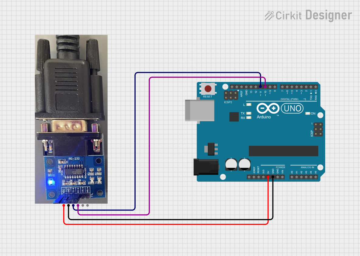
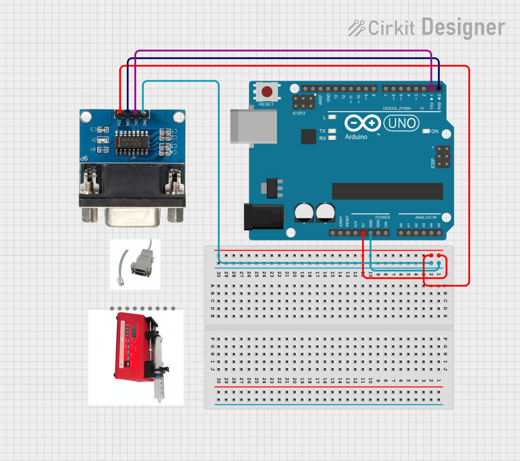
  1. Connect the VCC pin to a +3.3V or +5V power supply.
  2. Connect the GND pin to the system ground.
  3. Connect the T1IN and T2IN pins to the TTL signal sources (e.g., microcontroller TX pins).
  4. Connect the R1OUT and R2OUT pins to the RS232 signal destinations (e.g., DB9 connector).
  5. Connect the R1IN and R2IN pins to the RS232 signal sources (e.g., DB9 connector).
  6. Connect the T1OUT and T2OUT pins to the TTL signal destinations (e.g., microcontroller RX pins).

Important Considerations and Best Practices

  • Ensure that the power supply voltage matches the voltage level required by the TTL side of your circuit.
  • Use decoupling capacitors close to the VCC and GND pins to filter out noise.
  • Avoid long wire runs for RS232 signals to minimize signal degradation.
  • Use proper ESD precautions when handling the converter to prevent damage.

Example Connection with Arduino UNO

// Example code for interfacing RS232 to TTL converter with Arduino UNO

#include <SoftwareSerial.h>

SoftwareSerial mySerial(10, 11); // RX, TX

void setup() {
  // Open serial communications:
  Serial.begin(9600);
  // Set the data rate for the SoftwareSerial port
  mySerial.begin(9600);
}

void loop() { // run over and over
  if (mySerial.available()) {
    Serial.write(mySerial.read());
  }
  if (Serial.available()) {
    mySerial.write(Serial.read());
  }
}

Troubleshooting and FAQs

Common Issues Users Might Face

  • No Data Transfer: Ensure that the TX and RX pins are correctly connected and not reversed.
  • Garbled Data: Check if the baud rates of the devices are matched and properly configured.
  • Power Issues: Verify that the VCC pin is supplied with the correct voltage.

Solutions and Tips for Troubleshooting

  • Double-check the wiring and connections.
  • Use a multimeter to verify the voltage levels on the VCC and GND pins.
  • Ensure that the baud rate settings in your code match the baud rate of the connected RS232 device.

FAQs

Q: Can I use this converter with a 3.3V system? A: Yes, the converter can operate with a supply voltage from 3.0V to 5.5V.

Q: Is this converter compatible with all RS232 devices? A: The converter should work with most RS232 devices, but always check the device specifications to ensure compatibility.

Q: How can I protect my circuit from ESD? A: Use ESD protection methods such as grounding yourself before handling, using ESD-safe workstations, and storing the component in anti-static bags.

Q: Can I use this converter for high-speed data transmission? A: The converter supports data rates up to 250 kbps, which is suitable for many applications but may not be sufficient for very high-speed requirements.