How to Use rectifier ac to dc: Examples, Pinouts, and Specs
Introduction
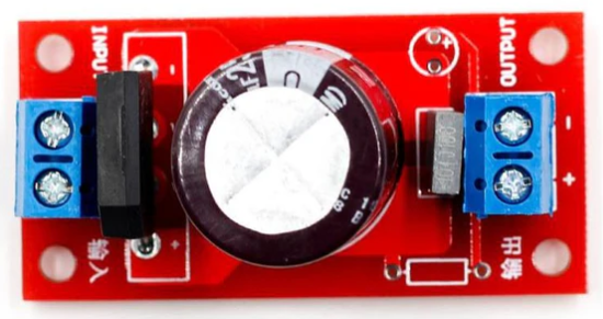
A rectifier AC to DC is an electronic component that converts alternating current (AC) into direct current (DC) by allowing current to flow in only one direction. This is typically achieved using diodes, which act as one-way valves for electrical current. Rectifiers are essential in power supply circuits, enabling the operation of DC-powered devices from an AC power source.
Explore Projects Built with rectifier ac to dc


Explore Projects Built with rectifier ac to dc
Common Applications and Use Cases
- Power supplies for electronic devices
- Battery charging circuits
- DC motor drives
- LED lighting systems
- Audio amplifiers and other DC-powered equipment
Technical Specifications
Key Technical Details
| Parameter | Value/Range |
|---|---|
| Input Voltage (AC) | Typically 110V-240V (varies by design) |
| Output Voltage (DC) | Depends on rectifier design (e.g., 5V, 12V, etc.) |
| Maximum Current Rating | Varies (e.g., 1A, 5A, 10A, etc.) |
| Efficiency | 80%-95% (depending on design and load) |
| Rectification Type | Half-wave, Full-wave, or Bridge |
| Ripple Factor | Depends on filtering (lower is better) |
| Operating Temperature | -40°C to +85°C (typical) |
Pin Configuration and Descriptions
For a bridge rectifier (a common type of AC to DC rectifier), the pin configuration is as follows:
| Pin Number | Label | Description |
|---|---|---|
| 1 | AC Input 1 | First AC input terminal |
| 2 | AC Input 2 | Second AC input terminal |
| 3 | DC Output + | Positive DC output terminal |
| 4 | DC Output - | Negative DC output terminal |
Usage Instructions
How to Use the Component in a Circuit
- Connect the AC Input Terminals: Attach the AC power source to the two AC input terminals of the rectifier. Ensure the voltage and current ratings of the rectifier match the input source.
- Connect the DC Output Terminals: Connect the positive and negative DC output terminals to the load or circuit requiring DC power.
- Add Filtering (Optional): To reduce ripple in the DC output, connect a capacitor (e.g., electrolytic capacitor) across the DC output terminals. The capacitor value depends on the load current and desired ripple reduction.
- Verify Connections: Double-check all connections to ensure proper polarity and avoid short circuits.
- Power On: Turn on the AC power source and measure the DC output voltage to confirm proper operation.
Important Considerations and Best Practices
- Heat Dissipation: High-current rectifiers may generate heat. Use a heatsink or cooling mechanism if necessary.
- Voltage Ratings: Ensure the rectifier's voltage rating exceeds the peak AC input voltage.
- Current Ratings: The rectifier's current rating should exceed the maximum load current to prevent damage.
- Polarity: Always observe correct polarity when connecting the DC output terminals to the load.
- Filtering: For sensitive applications, use additional filtering components (e.g., capacitors, inductors) to minimize ripple and noise.
Example: Using a Bridge Rectifier with Arduino UNO
To power an Arduino UNO from an AC source using a bridge rectifier, follow these steps:
- Connect the AC input terminals of the rectifier to the AC power source.
- Attach a filtering capacitor (e.g., 1000µF, 25V) across the DC output terminals.
- Connect the positive DC output terminal to the Arduino's VIN pin and the negative terminal to GND.
- Verify the DC output voltage is within the Arduino's acceptable input range (7-12V).
// Example code to blink an LED on Arduino UNO
// Ensure the rectifier provides a stable DC voltage to the Arduino

void setup() {
  pinMode(13, OUTPUT); // Set pin 13 as an output for the onboard LED
}

void loop() {
  digitalWrite(13, HIGH); // Turn the LED on
  delay(1000);            // Wait for 1 second
  digitalWrite(13, LOW);  // Turn the LED off
  delay(1000);            // Wait for 1 second
}
Troubleshooting and FAQs
Common Issues and Solutions
No DC Output:
- Check the AC input connections and ensure the power source is active.
- Verify the rectifier's voltage and current ratings match the input source.
- Inspect the rectifier for damage or faulty diodes.
Excessive Ripple in DC Output:
- Add or increase the value of the filtering capacitor.
- Ensure the capacitor's voltage rating is higher than the DC output voltage.
Overheating:
- Use a heatsink or cooling fan for high-current applications.
- Ensure the rectifier is not overloaded beyond its current rating.
Incorrect Polarity:
- Double-check the connections to the DC output terminals.
- Reverse polarity can damage the load or rectifier.
FAQs
Q: Can I use a rectifier without a filtering capacitor?
A: Yes, but the DC output will have significant ripple, which may not be suitable for sensitive devices.
Q: What type of rectifier should I use for high-power applications?
A: A bridge rectifier with a high current rating and proper cooling is recommended for high-power applications.
Q: How do I calculate the value of the filtering capacitor?
A: Use the formula:
( C = \frac{I}{f \cdot V_{ripple}} )
Where ( I ) is the load current, ( f ) is the AC frequency, and ( V_{ripple} ) is the allowable ripple voltage.
Q: Can I use a rectifier with a DC input?
A: No, rectifiers are designed for AC input. For DC-to-DC conversion, use a voltage regulator or DC-DC converter.