How to Use INA260: Examples, Pinouts, and Specs

Introduction
The INA260 is a high-side current shunt monitor with an integrated I2C interface, designed for precise measurement of voltage, current, and power. It features a built-in precision shunt resistor, eliminating the need for external components, and offers high accuracy across a wide input voltage range. The INA260 is ideal for power monitoring applications in industrial equipment, battery management systems, and consumer electronics.
Explore Projects Built with INA260

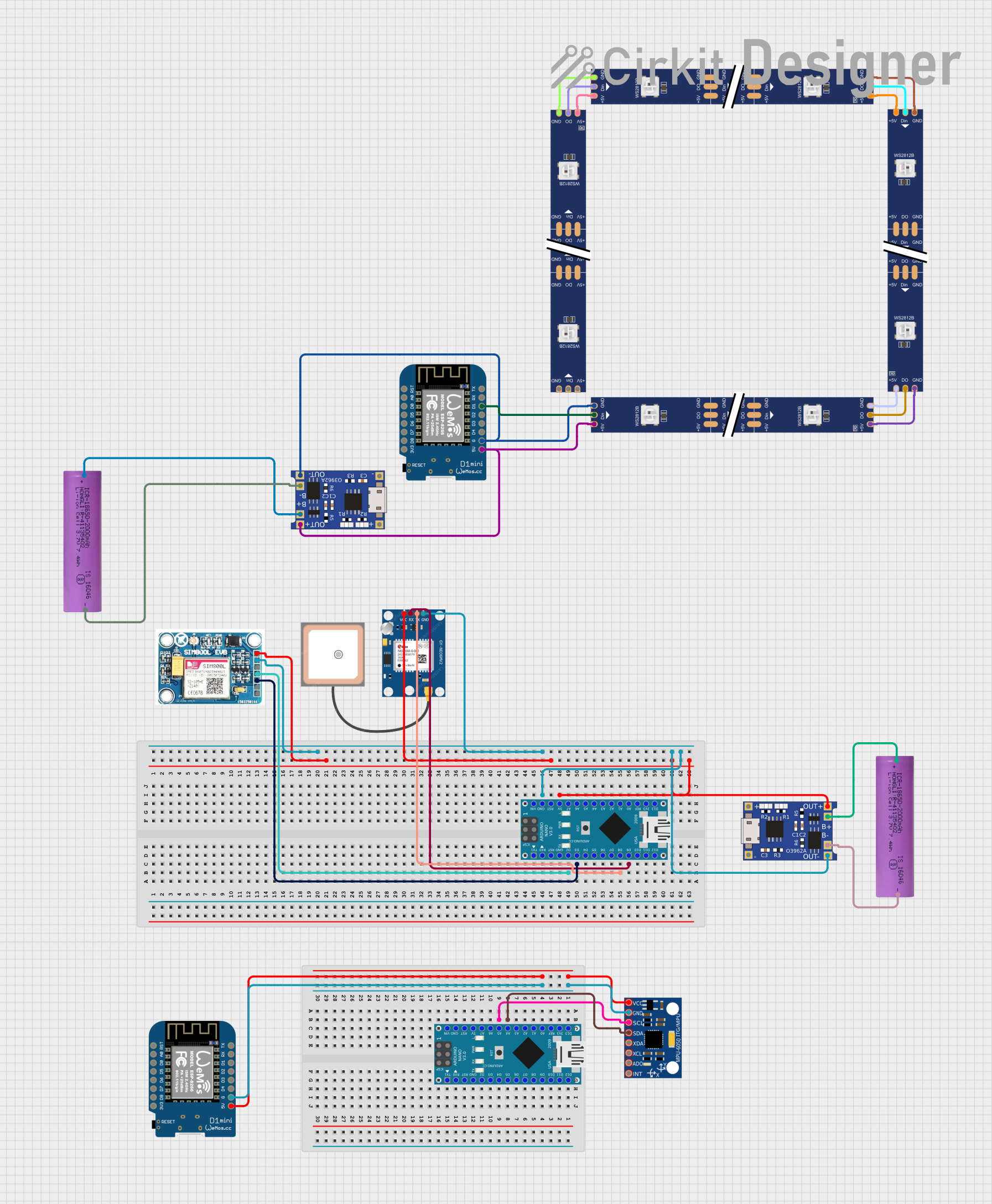

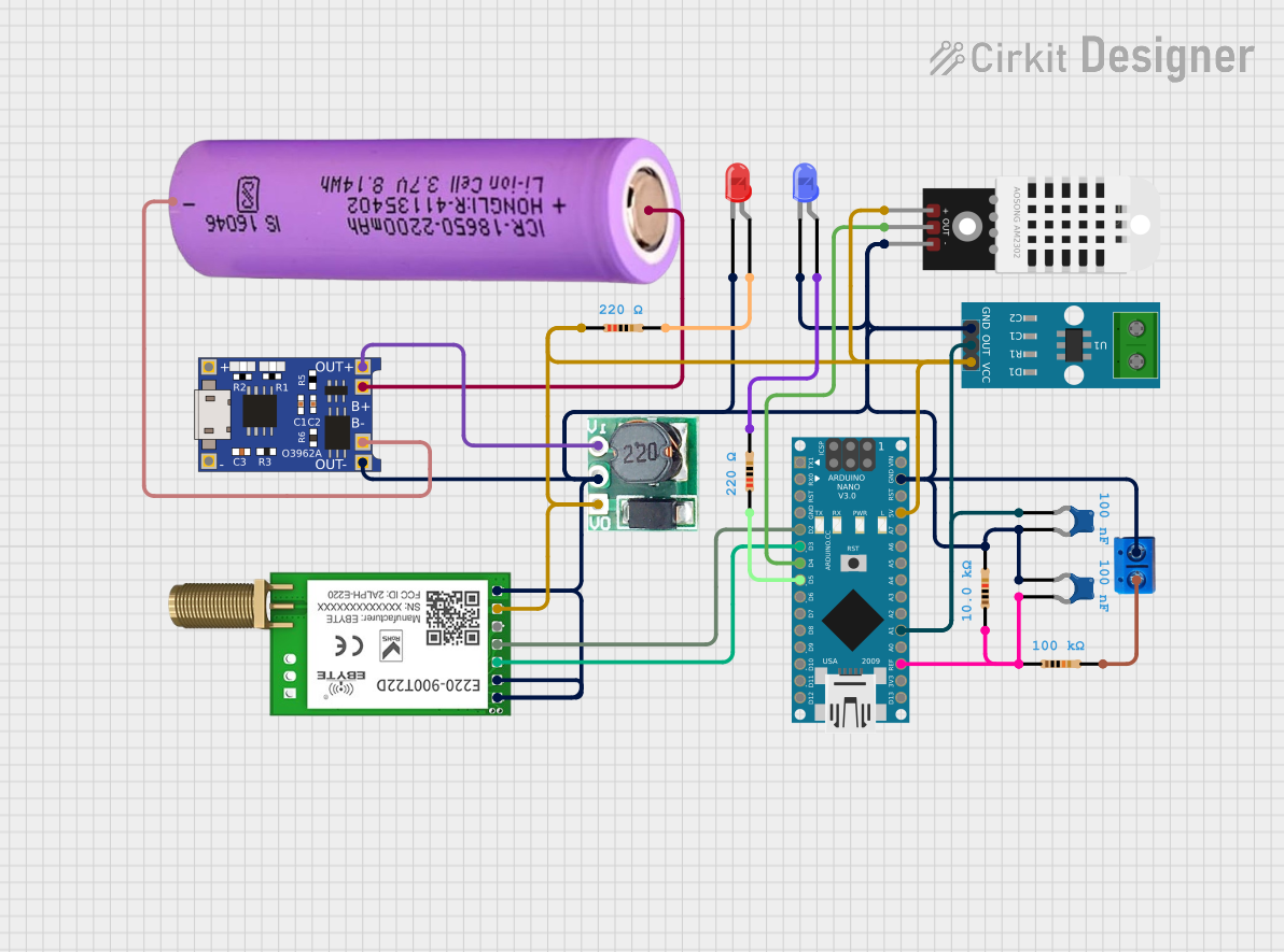
Explore Projects Built with INA260
Common Applications
- Power monitoring in servers and networking equipment
- Battery management systems
- Industrial automation and control systems
- Consumer electronics and IoT devices
Technical Specifications
Key Technical Details
- Supply Voltage (Vcc): 2.7V to 5.5V
- Input Voltage Range: 0V to 36V
- Current Measurement Range: ±15A (with integrated shunt resistor)
- Power Measurement Accuracy: ±0.1% (typical)
- Communication Interface: I2C (up to 1 MHz)
- Operating Temperature Range: -40°C to +125°C
- Integrated Shunt Resistor: 2 mΩ (±0.1% tolerance)
Pin Configuration and Descriptions
The INA260 is available in a 10-pin VSSOP package. Below is the pinout and description:
| Pin | Name | Type | Description |
|---|---|---|---|
| 1 | GND | Power | Ground connection. |
| 2 | VIN+ | Analog Input | Positive input for the voltage to be measured. |
| 3 | VIN- | Analog Input | Negative input for the voltage to be measured. |
| 4 | SDA | Digital I/O | I2C data line. |
| 5 | SCL | Digital Input | I2C clock line. |
| 6 | ALERT | Digital Output | Alert output for configurable over-limit conditions. |
| 7 | ADDR | Digital Input | Address pin for setting the I2C address. |
| 8 | NC | - | No connection. |
| 9 | VBUS | Analog Input | Voltage bus input for power measurement. |
| 10 | VCC | Power | Power supply input (2.7V to 5.5V). |
Usage Instructions
How to Use the INA260 in a Circuit
- Power Supply: Connect the VCC pin to a 3.3V or 5V power supply and the GND pin to ground.
- Voltage and Current Measurement:
- Connect the VIN+ and VIN- pins across the load or circuit where current is to be measured.
- The INA260 will measure the voltage drop across its internal shunt resistor to calculate current.
- I2C Communication:
- Connect the SDA and SCL pins to the corresponding I2C lines of your microcontroller.
- Use pull-up resistors (typically 4.7 kΩ) on the SDA and SCL lines if not already present.
- I2C Address Configuration:
- Use the ADDR pin to set the I2C address. This allows multiple INA260 devices to share the same I2C bus.
- Alert Functionality:
- The ALERT pin can be configured to trigger when a user-defined threshold for voltage, current, or power is exceeded.
Important Considerations
- Ensure the input voltage (VIN+ and VIN-) does not exceed the specified range of 0V to 36V.
- Avoid exceeding the ±15A current measurement range to prevent damage to the internal shunt resistor.
- Use proper decoupling capacitors (e.g., 0.1 µF) near the VCC pin to reduce noise.
Example Code for Arduino UNO
Below is an example of how to interface the INA260 with an Arduino UNO using the Wire library:
#include <Wire.h>

#define INA260_ADDRESS 0x40 // Default I2C address of the INA260

void setup() {
  Wire.begin(); // Initialize I2C communication
  Serial.begin(9600); // Initialize serial communication for debugging

  // Configure INA260 (optional: default settings are usually sufficient)
  Wire.beginTransmission(INA260_ADDRESS);
  Wire.write(0x00); // Point to configuration register
  Wire.write(0x61); // Set configuration (e.g., averaging, conversion time)
  Wire.write(0x27); // Complete configuration settings
  Wire.endTransmission();

  Serial.println("INA260 Initialized");
}

void loop() {
  // Request current measurement
  Wire.beginTransmission(INA260_ADDRESS);
  Wire.write(0x01); // Point to current register
  Wire.endTransmission();
  Wire.requestFrom(INA260_ADDRESS, 2); // Request 2 bytes of data

  if (Wire.available() == 2) {
    int16_t currentRaw = (Wire.read() << 8) | Wire.read(); // Combine MSB and LSB
    float current = currentRaw * 1.25 / 1000; // Convert to Amperes (1.25 mA/LSB)
    Serial.print("Current: ");
    Serial.print(current);
    Serial.println(" A");
  }

  delay(1000); // Wait 1 second before next reading
}
Notes:
- The example assumes the INA260 is at its default I2C address (0x40). Adjust the address if needed.
- The configuration register settings in the code are optional and can be modified based on application requirements.
Troubleshooting and FAQs
Common Issues and Solutions
No I2C Communication:
- Ensure the SDA and SCL lines are properly connected to the microcontroller.
- Verify that pull-up resistors are present on the I2C lines.
- Check the I2C address of the INA260 and ensure it matches the address in your code.
Incorrect Current or Voltage Readings:
- Verify that the input voltage (VIN+ and VIN-) is within the specified range.
- Ensure the load current does not exceed the ±15A range.
- Check for loose or incorrect connections.
Alert Pin Not Triggering:
- Confirm that the alert functionality is properly configured in the INA260 registers.
- Verify that the threshold values for voltage, current, or power are correctly set.
FAQs
Q: Can the INA260 measure negative currents?
A: Yes, the INA260 can measure both positive and negative currents, as it supports bidirectional current sensing.Q: How many INA260 devices can I connect to a single I2C bus?
A: Up to 16 INA260 devices can be connected to the same I2C bus by configuring their ADDR pins to different addresses.Q: What is the resolution of the current measurement?
A: The INA260 provides a resolution of 1.25 mA per least significant bit (LSB).Q: Is the internal shunt resistor replaceable?
A: No, the shunt resistor is integrated into the INA260 and cannot be replaced.
By following this documentation, users can effectively integrate the INA260 into their projects for accurate power monitoring.