How to Use Arduino Pro: Examples, Pinouts, and Specs
Introduction
The Arduino Pro is a compact microcontroller board based on the ATmega328P microcontroller. It is designed for advanced users who require a small form factor for their Arduino projects. The Arduino Pro is ideal for embedding into projects where space is a premium and where the board will be permanently installed.
Common applications for the Arduino Pro include wearable technology, portable instrumentation, custom embedded systems, and high-performance prototypes.
Explore Projects Built with Arduino Pro
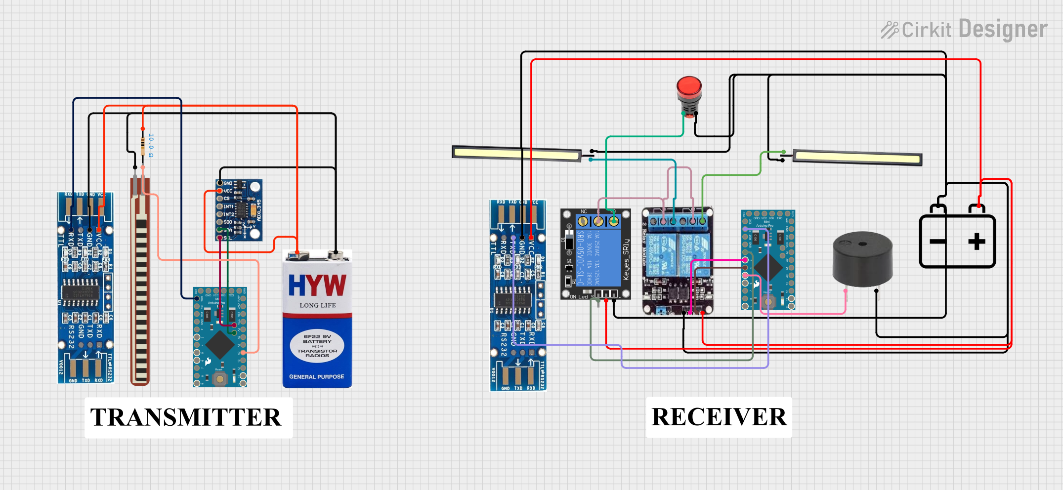
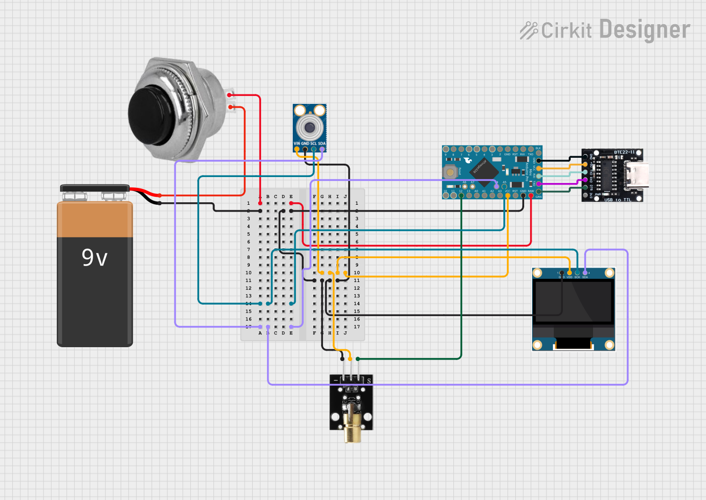
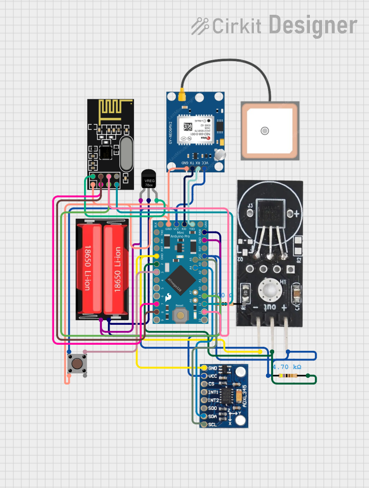
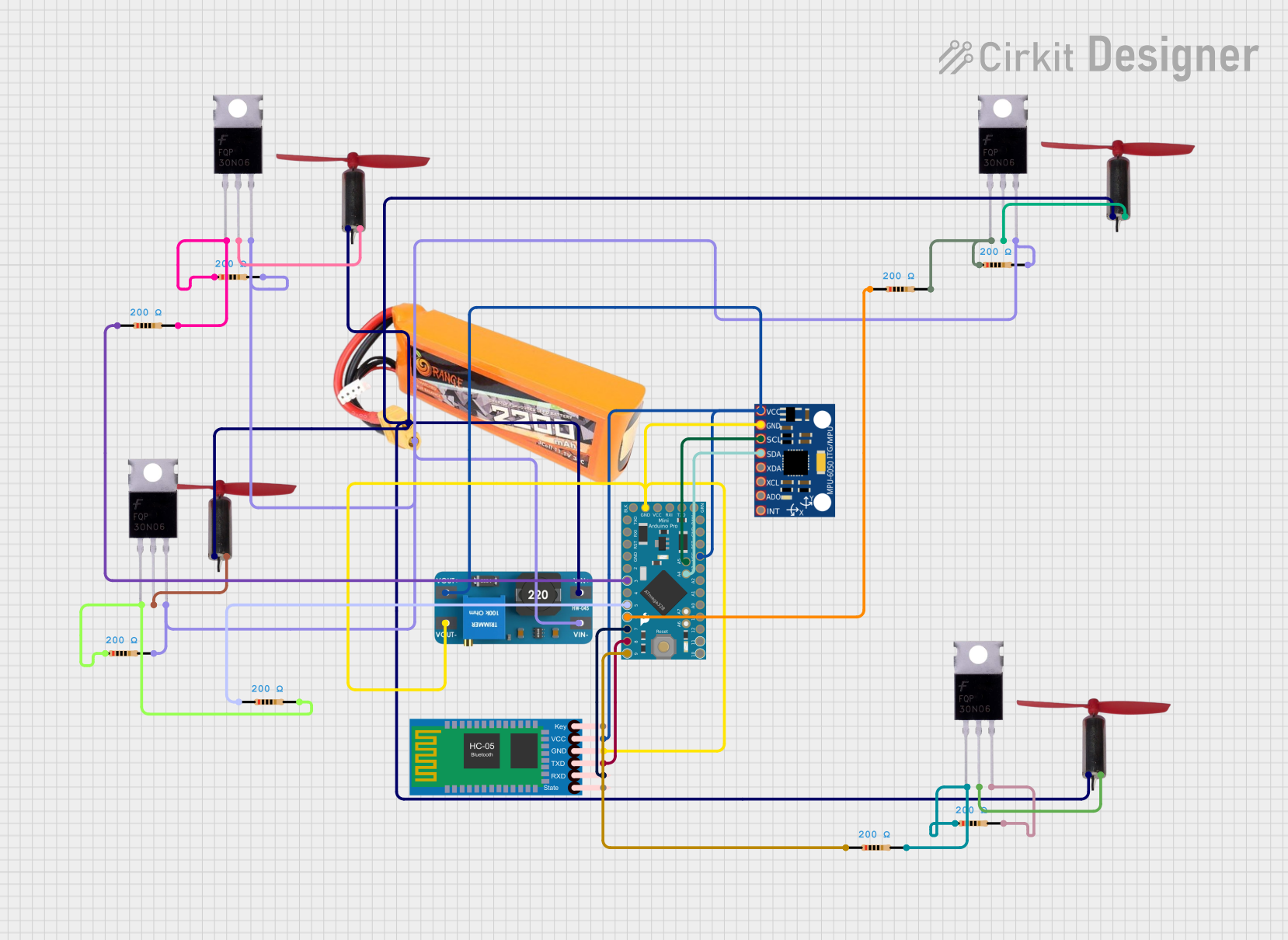
Explore Projects Built with Arduino Pro
Technical Specifications
Key Technical Details
- Microcontroller: ATmega328P
- Operating Voltage: 3.3V or 5V (depending on the model)
- Input Voltage (recommended): 5V - 12V
- Input Voltage (limits): 3.35V - 12V
- Digital I/O Pins: 14 (of which 6 provide PWM output)
- Analog Input Pins: 6
- DC Current per I/O Pin: 40 mA
- DC Current for 3.3V Pin: 50 mA
- Flash Memory: 32 KB (ATmega328P) of which 0.5 KB used by bootloader
- SRAM: 2 KB (ATmega328P)
- EEPROM: 1 KB (ATmega328P)
- Clock Speed: 8 MHz (3.3V model) or 16 MHz (5V model)
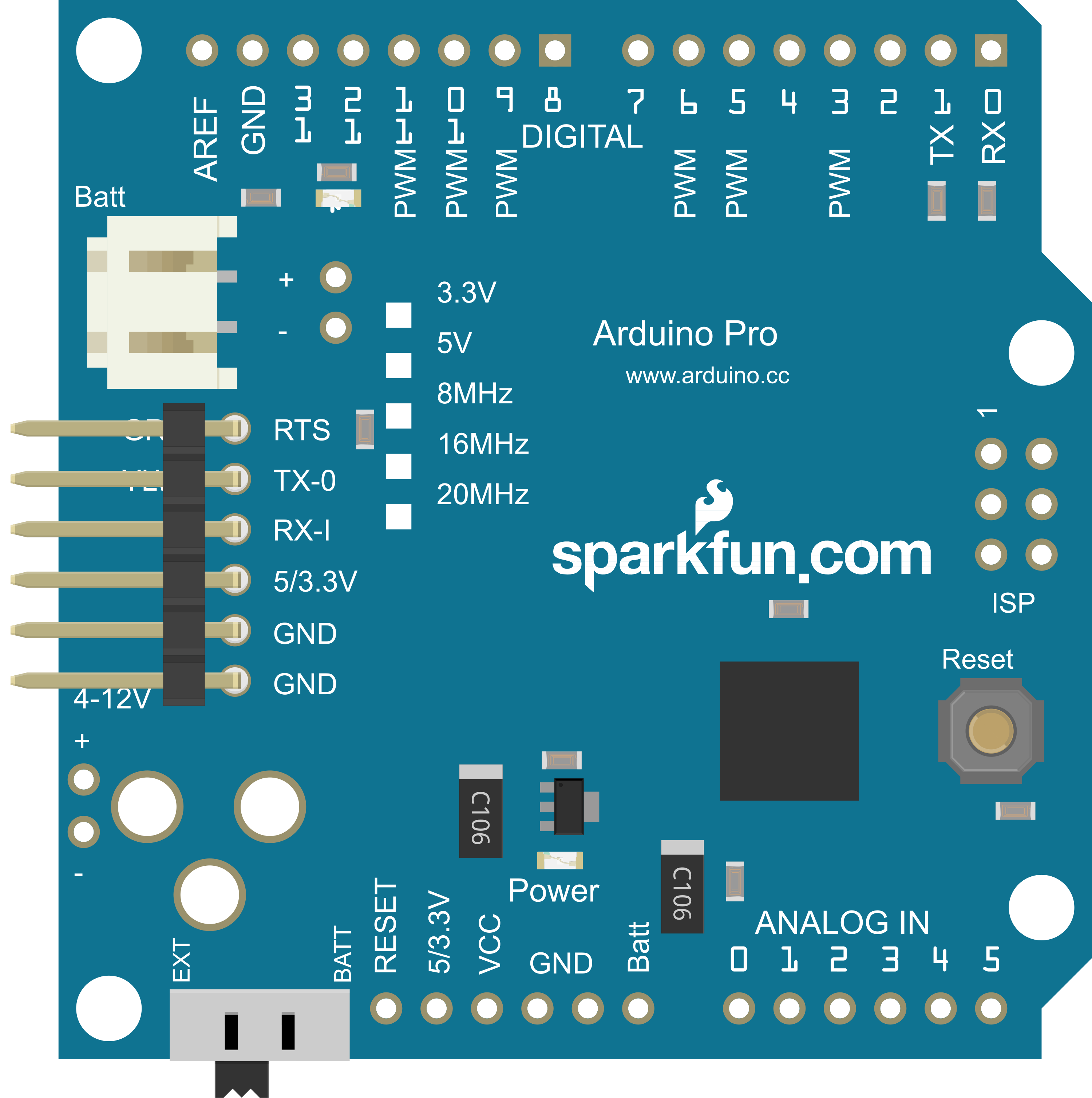
Pin Configuration and Descriptions
| Pin Number | Function | Description |
|---|---|---|
| 1 | RESET | Used to reset the microcontroller |
| 2-13 | Digital Pins | Digital input/output pins, PWM on pins 3, 5, 6, 9, 10, and 11 |
| 14-19 | Analog Pins | Analog input pins (A0-A5) |
| 20 | AREF | Analog reference voltage for the ADC |
| 21 | GND | Ground |
| 22 | AREF | Analog reference voltage for the ADC |
| 23 | 3.3V | 3.3V power supply pin (3.3V model only) |
| 24 | 5V | 5V power supply pin (5V model only) |
| 25 | GND | Ground |
| 26 | Vin | Input voltage to the Arduino board |
Usage Instructions
Integrating Arduino Pro into a Circuit
- Powering the Board: The Arduino Pro can be powered via the Vin pin with a regulated 5V to 12V supply, or directly to the 3.3V or 5V pin if a regulated voltage is available.
- Programming the Board: Use a USB-to-serial converter to connect the Arduino Pro to a computer for programming.
- Connecting I/O: Connect sensors, actuators, and other components to the digital and analog pins as required for your project.
Best Practices
- Ensure that the power supply is within the recommended limits to prevent damage.
- Use a current limiting resistor when connecting LEDs to the digital pins.
- Avoid drawing more than 40 mA from any single I/O pin.
- Utilize the onboard reset button or the RESET pin for troubleshooting and resetting the board.
Troubleshooting and FAQs
Common Issues
- Board not recognized by computer: Ensure that the USB-to-serial converter drivers are installed and that the correct board and port are selected in the Arduino IDE.
- Incorrect voltages at I/O pins: Verify that the board is powered correctly and that the power supply is stable.
- Sketch not running: Check the board's connection to the computer, ensure the correct board is selected in the IDE, and that the sketch is uploaded successfully.
Solutions and Tips
- If the Arduino Pro is not responding, try pressing the reset button or cycling the power.
- For issues with uploading sketches, double-check the connections between the Arduino Pro and the USB-to-serial converter.
- Ensure that the bootloader is correctly installed on the ATmega328P. If necessary, re-burn the bootloader using an ISP programmer.
Example Code for Arduino UNO
// Blink an LED connected to pin 13 of the Arduino Pro

void setup() {
  pinMode(13, OUTPUT); // Initialize pin 13 as an output
}

void loop() {
  digitalWrite(13, HIGH); // Turn the LED on
  delay(1000);           // Wait for a second
  digitalWrite(13, LOW);  // Turn the LED off
  delay(1000);           // Wait for a second
}
Note: The above code is for illustrative purposes and assumes that an LED is connected to pin 13 with a suitable current-limiting resistor.
For further assistance or questions, users are encouraged to consult the Arduino community forums or the extensive online resources available for the Arduino platform.