How to Use PCM5102A I2S DAC: Examples, Pinouts, and Specs
Introduction
The PCM5102A is a high-performance digital-to-analog converter (DAC) manufactured by Generic. It is designed to convert digital audio signals into high-quality analog audio output. The device supports the I2S (Inter-IC Sound) protocol for audio data input and is capable of processing 32-bit audio with sampling rates up to 384 kHz. With its low distortion, low noise, and high dynamic range, the PCM5102A is ideal for high-fidelity audio applications.
Explore Projects Built with PCM5102A I2S DAC

Explore Projects Built with PCM5102A I2S DAC
Common Applications
- High-end audio systems
- Digital music players
- Audio interfaces
- Home theater systems
- Embedded audio solutions
Technical Specifications
Key Technical Details
| Parameter | Value |
|---|---|
| Manufacturer Part ID | PCM5102A |
| Input Protocol | I2S |
| Audio Resolution | Up to 32-bit |
| Sampling Rate | Up to 384 kHz |
| Signal-to-Noise Ratio (SNR) | 112 dB |
| Total Harmonic Distortion + Noise (THD+N) | -93 dB |
| Power Supply Voltage | 3.3V (typical) |
| Output Voltage | 2.1 Vrms (typical) |
| Operating Temperature Range | -25°C to 85°C |
| Package Type | TSSOP-20 |
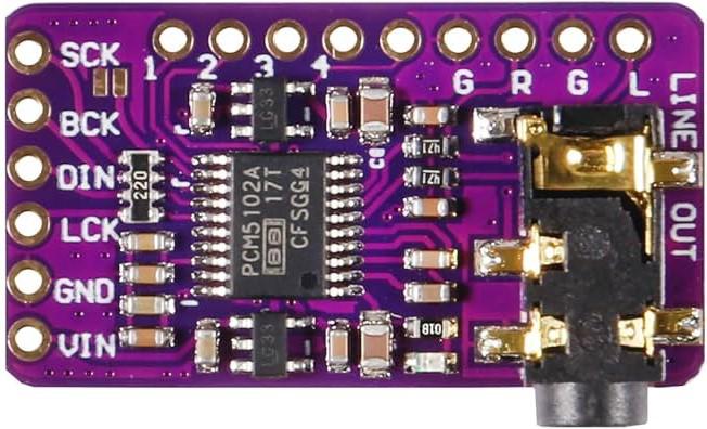
Pin Configuration and Descriptions
The PCM5102A comes in a 20-pin TSSOP package. Below is the pin configuration:
| Pin Number | Pin Name | Description |
|---|---|---|
| 1 | DVDD | Digital power supply (3.3V) |
| 2 | DGND | Digital ground |
| 3 | LRCK | Left/Right clock input for I2S |
| 4 | BCK | Bit clock input for I2S |
| 5 | DIN | Serial data input for I2S |
| 6 | SCK | System clock input (optional) |
| 7 | FMT | Audio format selection |
| 8 | XSMT | Soft mute control |
| 9 | FLT | Filter response selection |
| 10 | VCOM | Common-mode voltage output |
| 11 | VOUTL | Left channel analog output |
| 12 | VOUTR | Right channel analog output |
| 13 | AGND | Analog ground |
| 14 | AVDD | Analog power supply (3.3V) |
| 15 | NC | No connection |
| 16 | NC | No connection |
| 17 | NC | No connection |
| 18 | NC | No connection |
| 19 | NC | No connection |
| 20 | NC | No connection |
Usage Instructions
How to Use the PCM5102A in a Circuit
- Power Supply: Connect the digital (DVDD) and analog (AVDD) power supply pins to a stable 3.3V source. Ensure proper decoupling capacitors are placed close to the power pins to minimize noise.
- Grounding: Connect DGND and AGND to a common ground plane to avoid ground loops.
- I2S Interface:
- Connect the I2S signals (LRCK, BCK, and DIN) from your microcontroller or audio source to the corresponding pins on the PCM5102A.
- If a system clock (SCK) is required, provide a stable clock signal to the SCK pin.
- Audio Output: Connect the VOUTL and VOUTR pins to the left and right audio output channels, respectively. Use appropriate filtering or amplification circuits if needed.
- Control Pins:
- Use the FMT pin to select the desired audio format (e.g., I2S, left-justified, right-justified).
- Use the XSMT pin to enable or disable the soft mute feature.
- Use the FLT pin to select the desired filter response (e.g., sharp or slow roll-off).
Important Considerations and Best Practices
- Decoupling: Place decoupling capacitors (e.g., 0.1 µF and 10 µF) close to the power supply pins to reduce noise and ensure stable operation.
- PCB Layout: Use a ground plane and keep the analog and digital sections of the circuit isolated to minimize interference.
- Clock Signal: Ensure the I2S clock signals (LRCK, BCK, and SCK) are clean and free from jitter to maintain audio quality.
- Output Loading: Avoid connecting heavy loads directly to the VOUTL and VOUTR pins. Use a buffer or amplifier if necessary.
Example: Connecting PCM5102A to an Arduino UNO
The PCM5102A can be interfaced with an Arduino UNO using the I2S protocol. Below is an example code snippet to output audio data:
#include <I2S.h> // Include the I2S library for Arduino

void setup() {
  // Initialize the I2S interface
  if (!I2S.begin(I2S_PHILIPS_MODE, 44100, 32)) {
    // Check if I2S initialization failed
    while (1) {
      // Stay in an infinite loop if initialization fails
    }
  }
}

void loop() {
  // Generate a simple sine wave for testing
  for (int i = 0; i < 360; i++) {
    // Calculate the sine wave value
    int sample = 32767 * sin(i * PI / 180);
    // Write the sample to the I2S DAC
    I2S.write(sample);
  }
}
Note: The Arduino UNO requires an external I2S interface module, as it does not natively support I2S. Use an I2S-compatible microcontroller (e.g., ESP32) for direct interfacing.
Troubleshooting and FAQs
Common Issues and Solutions
No Audio Output:
- Verify that the power supply connections (DVDD and AVDD) are correct and stable.
- Check the I2S connections (LRCK, BCK, and DIN) for proper wiring and signal integrity.
- Ensure the audio source is configured to output I2S data in a compatible format.
Distorted Audio:
- Verify that the I2S clock signals (LRCK, BCK, and SCK) are free from jitter.
- Check the output load on VOUTL and VOUTR. Use a buffer or amplifier if needed.
- Ensure the power supply is clean and free from noise.
Device Overheating:
- Check for excessive current draw. Ensure proper decoupling capacitors are in place.
- Verify that the power supply voltage does not exceed the recommended 3.3V.
FAQs
Q1: Can the PCM5102A operate without an external system clock (SCK)?
A1: Yes, the PCM5102A can operate in master mode without an external SCK. However, for optimal performance, it is recommended to provide a stable system clock.
Q2: What audio formats does the PCM5102A support?
A2: The PCM5102A supports I2S, left-justified, and right-justified audio formats. The format can be selected using the FMT pin.
Q3: Can I use the PCM5102A with a 5V microcontroller?
A3: Yes, but you must use level shifters to convert the 5V logic signals to 3.3V, as the PCM5102A operates at 3.3V logic levels.
Q4: What is the maximum sampling rate supported by the PCM5102A?
A4: The PCM5102A supports sampling rates up to 384 kHz. Ensure your audio source and I2S interface are configured accordingly.