How to Use Adafruit LPS35HW: Examples, Pinouts, and Specs
Introduction
The Adafruit LPS35HW is a state-of-the-art pressure sensor module capable of measuring barometric pressure and ambient temperature with high precision. This compact sensor is ideal for a wide range of applications, including weather stations, altitude measurements for drones, indoor navigation, and fitness trackers. Its low power consumption and support for both I2C and SPI communication interfaces make it versatile for use in embedded systems, particularly those that require long battery life.
Explore Projects Built with Adafruit LPS35HW


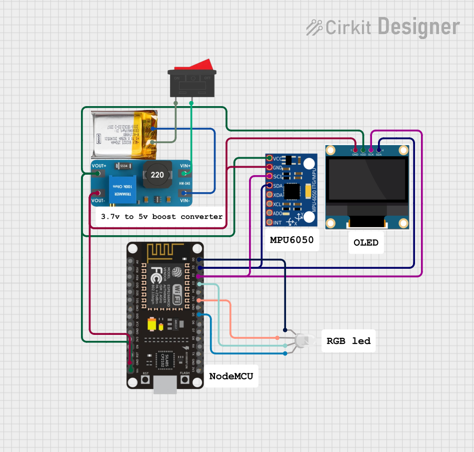
Explore Projects Built with Adafruit LPS35HW
Technical Specifications
Key Features
- Pressure Range: 260 to 1260 hPa
- Temperature Range: -40 to 85°C
- Resolution: 0.01 hPa
- Absolute Pressure Accuracy: ±0.1 hPa
- Supply Voltage: 1.7V to 3.6V
- Interface: I2C (up to 400 kHz), SPI (up to 10 MHz)
- Operating Current: 3 µA (low power mode)
- Communication Protocols: I2C and SPI
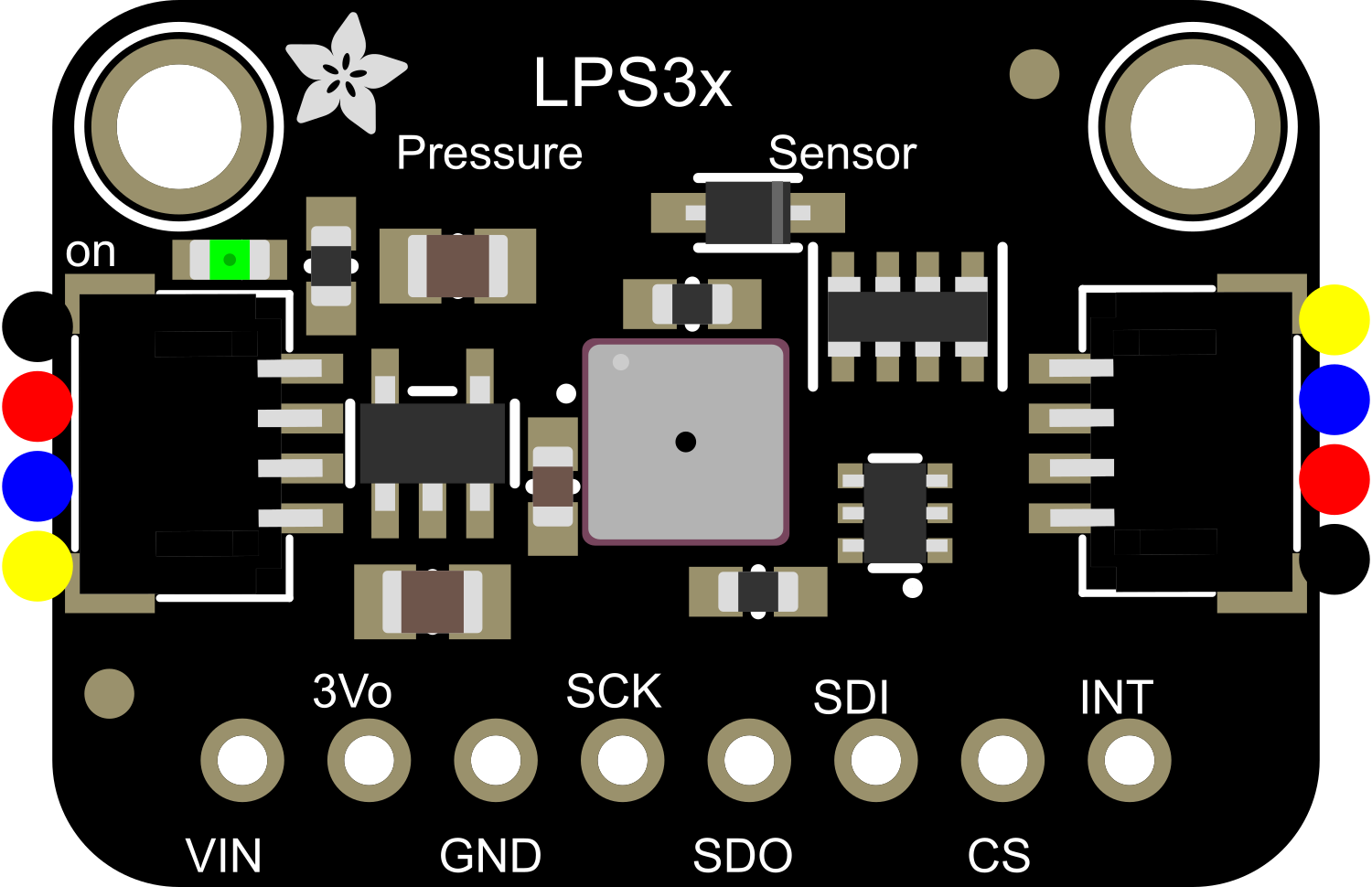
Pin Configuration and Descriptions
| Pin Number | Name | Description |
|---|---|---|
| 1 | VDD | Power supply (1.7V to 3.6V) |
| 2 | GND | Ground reference for the power supply |
| 3 | SDA | I2C Data Line / SPI Serial Data Out (SDO) |
| 4 | SCL | I2C Clock Line / SPI Serial Clock (SCK) |
| 5 | SA0 | I2C Address Selection / SPI Serial Data In (SDI) |
| 6 | CS | SPI Chip Select (active low) |
Usage Instructions
Integration into a Circuit
- Power Supply: Connect the VDD pin to a 1.7V to 3.6V power source and the GND pin to the ground of your circuit.
- Communication Interface:
- For I2C, connect SDA to your microcontroller's SDA line and SCL to the SCL line.
- For SPI, connect SDO, SDI, and SCK to the corresponding SPI pins on your microcontroller and CS to a digital pin designated for chip select.
- Address Selection: For I2C, the SA0 pin can be connected to either VDD or GND to select between two possible I2C addresses.
Best Practices
- Use pull-up resistors on the I2C data and clock lines.
- Keep the power supply stable and within the specified voltage range.
- Avoid physical stress and contamination on the sensor to maintain accuracy.
- Implement proper ESD precautions when handling the sensor.
Example Code for Arduino UNO
Below is an example code snippet for interfacing the Adafruit LPS35HW with an Arduino UNO using the I2C communication protocol.
#include <Wire.h>
#include <Adafruit_LPS35HW.h>

Adafruit_LPS35HW lps = Adafruit_LPS35HW();

void setup() {
  Serial.begin(9600);
  // Wait for serial monitor to open
  while (!Serial) { delay(10); }

  Serial.println("LPS35HW Test");

  if (!lps.begin_I2C()) { // Initialize over I2C
    Serial.println("Failed to find LPS35HW chip");
    while (1) { delay(10); }
  }
  Serial.println("LPS35HW Found!");
}

void loop() {
  Serial.print("Pressure: ");
  Serial.print(lps.readPressure());
  Serial.println(" hPa");

  Serial.print("Temperature: ");
  Serial.print(lps.readTemperature());
  Serial.println(" C");

  delay(500);
}
Ensure you have installed the Adafruit_LPS35HW library before uploading this code to your Arduino UNO.
Troubleshooting and FAQs
Common Issues
- Sensor Not Detected: Ensure that the wiring is correct and the sensor is properly powered.
- Inaccurate Readings: Check for physical obstructions or contaminants on the sensor. Recalibrate if necessary.
- Communication Errors: Verify that the correct communication protocol (I2C/SPI) is selected and properly configured.
FAQs
Q: Can the LPS35HW be used outdoors? A: Yes, but it should be protected from direct exposure to water and extreme environmental conditions.
Q: What is the default I2C address? A: The default I2C address is 0x5C when SA0 is connected to GND, and 0x5D when connected to VDD.
Q: How can I calibrate the sensor? A: Calibration procedures are detailed in the sensor's datasheet and typically involve taking readings at known pressure and temperature points.
For further assistance, consult the Adafruit LPS35HW datasheet and the Adafruit support forums.